LTCC low temperature co-fired ceramics for high frequency Microwave Filter,sensor,Vacuum Electronics
|
|
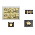
Coraynic Technology Limited is a professional and reliable LTCC/HTCC ceramic material, LTCC (low temperature co-fired ceramics) represents a multilayer ceramic substrate that is co-fired with a low resistance internal circuit made of a metal such as Ag or Cu, at temperatures lower than the melting points of this metal (less than 1,000°C). It can be defined as a way to produce multilayer circuits with the help of single tapes, which are used to apply conductive, dielectric, and/or resistive pastes.
LTCC is a multilayer ceramic technology with excellent dimensional accuracy, high density, high frequency, and reliability offering excellent RF and microwave performance characteristics. Its low sintering temperature (approximately 900°C) allows co-firing with highly conductive metals such as silver and gold. for moderate firing temperatures. The LTCC process is similar to the thick film hybrid process employed for multilayer ceramic capacitors and chip inductors. The moderate firing temperature level below 900 °C is achieved by mixing alumina and glass as the main ingredients of the ceramic tape, the so-called green sheets. This permits the co-firing with highly conductive material (silver) for the electrodes.LTCC also supports the creation of buried components and thus contributes to miniaturization.
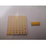
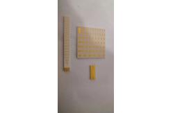
LTCC design rule size heat sink array
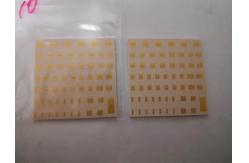
When designing high-frequency signal lines, you can achieve good
shielding by placing ground holes in parallel on both sides. As
shown below,
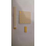
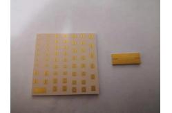
Production Process Tape castingLTCC producers usually use tapes shipped on a roll. Slitting A tape is unrolled and cut into individual pieces. For this purpose, Via holes punching (Punching machines)Vias may be punched or drilled with a laser. Via filling (P-series) in LTCC productionVias can be filled with a conventional thick film screen printer or an extrusion via filler. Conductive lines printing (P-series screen printer)Cofireable conductors etc are printed on the green sheet using a
thick film screen-printer. The screens are standard (250 – 400)
emulsion or foil-type thick film screens. |