
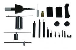
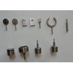
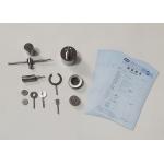
UL498 Plug Socket Measuring Gauge
|
Detailed Product Description
|
UL498 Plug And Socket Measuring Gauge For Retention Of Blades Test
UL498-2012 Figure 109.1 1 UL498-2012 Figure 109.1 1 UL498-2012 Figure 109.2 1 UL498-2012 Figure 123.3 1 UL498-2012 Figure 123.4 1 109 Retention of Blades Test 109.1 A flush or self-contained receptacle having a 5-15R, 5-20R,
6-15R, or 6-20R configuration shall be subjected to the retention of blades test described in this
Section. Exception: A receptacle having a 1-15R, 5-15R, 5-20R, 6-15R, or
6-20R configuration and not of the flush or self-contained type may instead be subjected to the
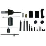
Retention of Plugs Test, Section 114. 109.1 revised November 16, 2012 109.2 Receptacles having the break-off tab, when provided, removed
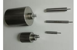
from one nonidentified terminal are to be subjected to ten conditioning cycles of manual insertion and
withdrawal of a standard gauge, see Figure 109.1. Each of six devices is to be tested. The gauge is to
be configured as outlined in Table 109.1. The force applied to insert the gauge for any of the conditioning
cycles is not to exceed 40 lbf (178 N). The gauge is to have the dimensions indicated in Figure 109.1 but
is not to have holes in the outer ends of the blades. Figure 109.1 Test gauge NOTES 1) Blades shall be made of tool steel, Rockwell Hardness C58 to
C60. 2) All sharp edges shall be removed to a radius of 0.016 to 0.020
inch. Ends of all flat blades bevelled as shown in the end of blade detail. 3) Blade surfaces shall not exceed a 32 microinch finish grind in a
direction perpendicular to the major axis. Finish is to be determined visually using a comparative method and 10 X optical
magnification. 4) All blade hole positions are located on the centerline of the
blades. 5) R designates radius. All dimensions are in inches. 6) Flat blade positions shall be modified to suit configurations
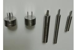
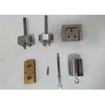
5-20 and 6-20. Table 109.1 Test gauge configurations for conditioning Device under test Test gauge No. of devices tested 5-15R 5-15P 6 5-20R 5-15P 3 5-20P 3 6-15R 6-15P 6 6-20R 6-15P 3 6-20P 3 109.3 The standard gauge is to be configured as shown in Table
109.2 using the line blades without holes and with the grounding blade removed. The gauge is then to be
inserted in the receptacle and a static 3 lbf (13.3 N) (including the weight of the gauge), which
tends to remove the gauge from the receptacle, is to be applied for a period of 1 minute in a
direction normal to the plane of the face of the receptacle. There shall not be more than 0.079 inch (2 mm)
displacement of the gauge. Table 109.2 Test gauge configurations for retention testing Device under test Test gauge No. of devices tested 5-15R 1-15P or 5-15Pa 6 5-20R 1-15P or 5-15Pa 3 5-20Pa 3 6-15R 2-15P or 6-15Pa 6 6-20R 2-15P or 6-15Pa 3 2-20P or 6-20Pa 3 a Test gauge having grounding blade removed. 109.4 The standard gauge is to be configured as shown in Table
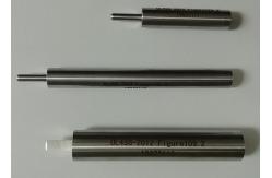
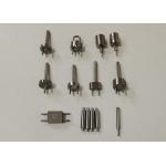
109.3 using the line blades with holes in the end and with the grounding blade in place. The gauge is then
to be inserted in the receptacle and a force applied in a direction normal to the plane of the face of
the receptacle that tends to remove the gauge. The static force required to withdraw the gauge shall not
exceed 15 lbf (67 N) (including the weight of the gauge). 109.2. Each line contact shall be capable of withstanding for 1
minute a static 0.5 lbf (2.2 N) applied to the test blade in a direction normal to the plane of the face of
the specimen and in a direction that tends to remove the test blade, when the test blade is fully inserted in
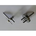
the contact opening. There shall not be more than 0.079 inch (2 mm) displacement of the test blade. Figure 123.3 2 oz (57 g) ground pin Material: Pin-Steel, Rockwell Hardness C58 to C60. Handle – cold rolled steel NOTES 1) The ground pin is to be fastened to handle in rigid manner. 2) Length not specified. Total tool weight 2 oz (57 g). 3) Axis of blade and axis of handle, must have combined
concentricity and axial alignment of 0.006 maximum at tip of pin. 4) The blade surfaces shall not exceed a 32 microinch finish grind
in a direction perpendicular to the major axis. Finish is to be determined visually using a comparative method and
10 X optical magnification. Figure 123.4 4 oz (113 g) ground pin Material: Pin-Steel, Rockwell Hardness C58 to C60. Handle – cold rolled steel NOTES 1) The ground pin is to be fastened to handle in rigid manner. 2) Length not specified. Total tool weight 4 oz (113 g). 3) Axis of blade and axis of handle, must have combined
concentricity and axial alignment of 0.006 maximum at tip of pin. 4) The blade surfaces shall not exceed a 32 microinch finish grind
in a direction perpendicular to the major axis. Finish is to be determined visually using a comparative method and
10 X optical magnification. Application:
|
||||||||||||||||||||||||||||||||||||||||||||||||||||||||||||||||||||||||||||||||||||||||||||||||||||||||||||||||
| Product Tags: UL498 Plug Socket Measuring Gauge Mold Steel Plug Socket Measuring Gauge UL498 Plug Socket Tester | ||||||||||||||||||||||||||||||||||||||||||||||||||||||||||||||||||||||||||||||||||||||||||||||||||||||||||||||||
Related Products
Email to this supplier