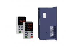
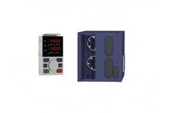
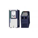
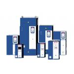
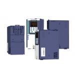
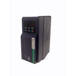
Fault Name | Fault code | Display | Possible Causes | Solutions |
Inverter unit protection | 1 | Er. SC | 1: motor insulation aging 2: the cable is damaged and contact, short circuit 3:The distance between motor and inverter are too long. 4: output transistor breakdown 5: the internal wiring of the inverter is loose, or the hardware is
bad. 6:brake transistor short circuit | 1. Confirm the insulation resistance of the motor. If it is turned
on, replace the motor. 2. Check the power cable of the motor 3. Install reactor or output filter 4, seeking technical support 5, seeking technical support 6. Check if the braking resistor is damaged and the wiring is
correct. |
Over current during acceleration | 2 | Er.OC1 | 1: The output circuit is grounded or short circuited. 2: Motor auto-tuning is not performed. 3: The acceleration time is too short. 4: Manual torque boost or V/F curve is not appropriate. 5: The voltage is too low. 6: The startup operation is performed on the rotating motor. 7: A sudden load is added during acceleration. 8: The frequency inverter model is of too small power class. | 1: Eliminate external faults. 2: Perform the motor auto- Tuning in cold state 3: Increase the acceleration time. 4: Adjust the manual torque boost or V/F curve. 5: Adjust the voltage to normal range. 6: Select rotational speed tracking restart or start the motor after it stops. 7: Remove the added load. 8: Select a frequency inverter Of higher power class. |
Over current during deceleration | 3 | Er.OC2 | 1: The output circuit is grounded or short circuited. 2: Motor auto-tuning is not performed. 3: The deceleration time is too short. 4: The voltage is too low. 5: A sudden load is added during deceleration. 6: The braking unit and braking resistor are not installed | 1: Eliminate external faults. 2: Perform the motor auto-tuning. 3: Increase the deceleration time. 4: Adjust the voltage to normal range. 5: Remove the added load. 6: Install the braking unit And braking resistor. |
Over current at constant speed | 4 | Er.OC3 | 1: The output circuit is grounded or short circuited. 2: Motor auto-tuning is notperformed. 3: The voltage is too low. 4: A sudden load is added during operation. 5: The frequency inverter model is of too small power class. | 1:Eliminate external faults. 2: Perform the motor auto-tuning. 3:Adjust The voltage to normal range. 4: Remove the addedload. 5: Select a frequency Inverter of higher power class. |
Overvoltage during acceleration | 5 | Er.OU1 | 1:the input voltage is too high 2:The surge voltage is mixed in the input power supply. 3: there is an external force to drive the motor to run, or the
brake type load is too heavy 4:the acceleration time is too short 5:the motor is shorted to ground | 1:the power supply voltage is reduced to the normal range 2:install DC reactor 3:Cancel the external force of the draggable motor or install the
brake unit 4: increase the acceleration time 5:eliminate the part of the ground short circuit |
Overvoltage during deceleration | 6 | Er.OU2 | 1:the input voltage is too high 2:The surge voltage is mixed in the input power supply. 3: there is an external force to drive the motor to run, or the
brake type load is too heavy 4:the decceleration time is too short 5:the motor is shorted to ground | 1:the power supply voltage is reduced to the normal range 2:install DC reactor 3:Cancel the external force of the draggable motor or install the
brake unit 4: increase the decceleration time 5:eliminate the part of the ground |
Overvoltage at constant speed | 7 | Er.OU3 | 1:the input voltage is too high 2:The surge voltage is mixed in the input power supply. 3: there is an external force to drive the motor to run, or the
brake type load is too heavy 4:the acceleration or decceleration time is too short 5:the motor is shorted to ground | 1:the power supply voltage is reduced to the normal range 2:install DC reactor 3:Cancel the external force of the draggable motor or install the
brake unit 4: increase the acceleration or decceleration time 5:eliminate the part of the ground |
Low voltage | 8 | Er.Lv1 | 1: Instantaneous power failure occurs on the input power supply or input phase loss 2: The frequency inverter's input voltage is not within the allowable range. 3: cut off the power during operation 4:the internal wiring of the inverter is loose, or the hardware is
bad. | 1:Check if the input power supply is abnormal, whether the input
power terminal is loose, whether the input contactor or the air
switch is abnormal. 2:adjust the voltage to the normal range 3:Power off after the inverter stops 4:seeking technical support 5: For the unstable power supply, if the performance requirements
are low, try to enable the undervoltage stall function (P23.00). |
Contactor open | 9 | Er.Lv2 | 1: Instantaneous power failure occurs on the input power supply 2: The frequency inverter's input voltage is not within the allowable range. 3: cut off the power during operation 4:the internal wiring of the inverter is loose, or the hardware is
bad. | 1:Check if the input power supply is abnormal, whether the input
power terminal is loose, whether the input contactor or the air
switch is abnormal. 2:adjust the voltage to the normal range 3:Power off after the inverter stops 4:seeking technical support 5: For the unstable power supply, if the performance requirements
are low, try to enable the undervoltage stall function (P23.00). |
Frequency inverter overload | 10 | Er. oL | 1:The load is too large or the motor is blocked. 2:the large inertia load acceleration and deceleration time is too
short 3: When the VF is controlled, the torque boost or V/F curve is not
suitable. 4:the frequency converter selection is too small 5:overload at low speed operation | 1. Reduce the load and check the motor and mechanical conditions. 2, increase the acceleration and deceleration time 3. Adjust the torque boost or V/F curve 4, select the inverter with a larger power level 5. Perform motor self-learning in cold state and reduce carrier
frequency at low speed |
Motor overload | 11 | Er.oL1 | 1:The load is too large or the motor is blocked. 2:the large inertia load acceleration and deceleration time is too
short 3:When the VF is controlled, the torque boost or V/F curve is not
suitable. 4:the motor selection is too small 5:overload at low speed operation 6:Improper setting of motor parameters and motor protection
parameters | 1. Reduce the load and check the motor and mechanical conditions.
Correctly set the motor parameters and motor protection parameters. 2, increase the acceleration and deceleration time 3. Adjust the torque boost or V/F curve 4, select a motor with a higher power level 5. Perform motor self-learning in cold state and reduce carrier
frequency at low speed 6, check the settings of related parameters |