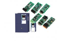
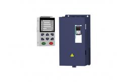
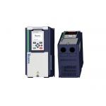
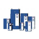
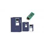
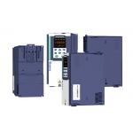
30kw 40hp 220v 380v variable frequency drive VFD three phase single
phase VEIKONG VFD500 Technical data: | Item | Specifiation | | Input | Inuput Voltage | 1phase/3phase 220V:200V~240V 3 phase 380V-480V:380V~480V | | | Allowed Voltage fluctuation range | -15%~10% | | | Input frequency | 50Hz / 60Hz,fluctuation less than 5% | | Output | Output Voltage | 3phase:0~input voltage | | | Overload capacity | General purpose application:60S for 150% of the rated current Light load application:60S for 120% of the rated current | | Control | Control mode | V/f control Sensorless flux vector control without PG card(SVC) Sensor speed flux vector control with PG card (VC) | | | Operating mode | Speed control,Torque control(SVC and VC) | | | Speed range | 1:100 (V/f) 1:200( SVC) 1:1000 (VC) | | | Speed control accuracy | ±0.5% (V/f) ±0.2% (SVC) ±0.02% (VC) | | | Speed response | 5Hz(V/f) 20Hz(SVC) 50Hz(VC) | | | frequency range | 0.00~600.00Hz(V/f) 0.00~200.00Hz(SVC) 0.00~400.00Hz(VC) | | | Input frequency resolution | Digital setting: 0.01 Hz Analog setting: maximum frequency x 0.1% | | | Startup torque | 150%/0.5Hz(V/f) 180%/0.25Hz(SVC) 200%/0Hz(VC) | | | Torque control accuracy | SVC:within 5Hz10%,above 5Hz5% VC:3.0% | | | V/f curve | V / f curve type: straight line, multipoint, power function, V / f
separation; Torque boost support: Automatic torque boost (factory setting),
manual torque boost | | | Frequency giving ramp | Support linear and S curve acceleration and deceleration; 4 groups of acceleration and deceleration time, setting range 0.00s
~ 60000s | | | DC bus voltage control | Overvoltage stall control: limit the power generation of the motor
by adjusting the output frequency to avoid skipping the voltage
fault; Undervoltage stall control: control the power consumption of the
motor by adjusting the output frequency to avoid yaw failure VdcMax Control: Limit the amount of power generated by the motor by
adjusting the output frequency to avoid over-voltage trip; VdcMin control: Control the power consumption of the motor by
adjusting the output frequency, to avoid jump undervoltage fault | | | Carrier frequency | 1kHz~12kHz(Varies depending on the type) | | | Startup method | Direct start (can be superimposed DC brake); speed tracking start |
| | Stop method | Deceleration stop (can be superimposed DC braking); free to stop | | Maincontrol function | Jog control, droop control, up to 16-speed operation, dangerous
speed avoidance, swing frequency operation, acceleration and
deceleration time switching, VF separation, over excitation
braking, process PID control, sleep and wake-up function, built-in
simple PLC logic, virtual Input and output terminals, built-in
delay unit, built-in comparison unit and logic unit, parameter
backup and recovery, perfect fault record,fault reset, two groups
of motor parametersfreeswitching, software swap output wiring,
terminals UP / DOWN | | Function | Keypad | LED Digital keyboard and LCD keypad(option) | | Communication | Standard: MODBUS communication CAN OPEN AND PROFINET( IN DEVELOPMENT) | | PG card | Incremental Encoder Interface Card (Differential Output and Open
Collector), Rotary transformer Card | | Input terminal | Standard: 5 digital input terminals, one of which supports high-speed pulse
input up to 50kHz; 2 analog input terminals, support 0 ~ 10V voltage input or 0 ~ 20mA
current input; Option card: 4 digital input terminals 2 analog input terminals.support-10V-+10V voltage input | | Output terminal | standard: 1 digital output terminal; 1 high-speed pulse output terminal (open collector type), support 0
~ 50kHz square wave signal output; 1 relay output terminal(second relay is an option ) 2 analog output terminals, support 0 ~ 20mA current output or 0 ~
10V voltage output; Option card: 4 digital output terminals | | Protection | Refer to Chapter 6 "Troubleshooting and Countermeasures" for the
protection function | | Environment | Installation location | Indoor, no direct sunlight, dust, corrosive gas, combustible gas,
oil smoke, vapor, drip or salt. | | Altitude | 0-3000m.inverter will be derated if altitude higher than1000m and
rated output current will reduce by 1% if altitude increase by 100m | | Ambient temperature | -10°C~ +40°C,maximum 50°C (derated if the ambient temperature is
between 40°C and 50°C)Rated output current decrease by 1.5% if
temperature increase by 1°C | | Humidity | Less than 95%RH, without condensing | | Vibration | Less than 5.9 m/s2 (0.6 g) | | Storage temperature | -20°C ~ +60°C | | Others | Installation | Wall-mounted, floor-controlled cabinet, transmural | | Protection level | IP20 | | cooling method | Forced air cooling | | EMC | CE ROHS | Internal EMC filter Complies with EN61800-3 Category C3 3rd Environment |
Replace famous brands vfd in general application. PID function | 40 Group PID function | | r40.00 | PID final output value | Read only unit:0.1% | - | ● | | r40.01 | PID final set value | Read only unit:0.1% | - | ● | | r40.02 | PID final feedback value | Read only unit:0.1% | - | ● | | r40.03 | PID deviation value | Read only unit:0.1% | - | ● |
| P40.04 | PID reference source | Unit’s digit:PID main reference source(ref1) 0:Digtital setting 1:AI1 2:AI2 3:AI3(IO expansion board) 4:AI4(IO expansion board) 5:HDI high frequency pulse 6:Communication Ten’s digit:PID Auxilary reference source(ref2)Same as Unit’s digit | 00 | ☆ | | P40.05 | PID given feedback range | 0.01~655.35 | 100.00 | ☆ | | P40.06 | PID digital setting 0 | 0.0~P40.05 | 0.0% | ☆ | | P40.07 | PID digital setting 1 | 0.0~P40.05 | 0.0% | ☆ | | P40.08 | PID digital setting 2 | 0.0~P40.05 | 0.0% | ☆ | | P40.09 | PID digital setting 3 | 0.0~P40.05 | 0.0% | ☆ | When PID reference source is digital setting, PID digital setting
0~3 depends on DI terminal function 43 (preset PID terminal I ) and
44 ( preset PID terminal 2): | preset PID terminal1 | preset PID terminal 2 | PID Digital setting value(0.1%) | | ineffective | ineffective | P40.06 * 100.0% / P40.05 | | ineffective | effective | P40.07 * 100.0% / P40.05 | | effective | ineffective | P40.08 * 100.0% / P40.05 | | effective | effective | P40.09 * 100.0% / P40.05 |
For example: When AI1 is used as PID feedback, if the full range
corresponds to 16.0kg pressure and require PID control to be 8.0kg;
then set P40.05 PID feedback range to 16.00, PID digital reference
terminal select to P40.06, Set P40.06 (PID preset setting 0) to be
8.00 |
When PID reference source is digital setting, PID digital setting
0~3 depends on DI terminal function 43 (preset PID terminal I ) and
44 ( preset PID terminal 2): | preset PID terminal1 | preset PID terminal 2 | PID Digital setting value(0.1%) | | ineffective | ineffective | P40.06 * 100.0% / P40.05 | | ineffective | effective | P40.07 * 100.0% / P40.05 | | effective | ineffective | P40.08 * 100.0% / P40.05 | | effective | effective | P40.09 * 100.0% / P40.05 |
For example: When AI1 is used as PID feedback, if the full range
corresponds to 16.0kg pressure and require PID control to be 8.0kg;
then set P40.05 PID feedback range to 16.00, PID digital reference
terminal select to P40.06, Set P40.06 (PID preset setting 0) to be
8.00 | | P40.10 | PID reference source selection | 0:ref1
1:ref1+ref2
2:ref1-ref2
3:ref1*ref2
4:ref1/ref2
5:Min(ref1,ref2)
6:Max(ref1,ref2)
7(ref1+ref2)/2
8: fdb1and fdb2 switchover | 0 | ☆ | | P40.11 | PID feedback source1 | Unit’s digit 0:PID feedback source1(fdb1) 0:AI1 1:AI2 2:AI3(option card) 3:AI4(option card) 4: PLUSE(HDI) 5: Communication 6: Motor rated output current 7: Motor rated output frequency 8: Motor rated output torque 9: Motor rated output frequency Ten’s digit : PID feedback source2 (fdb2) Same as Unit’s digit | 00 | ☆ | | P40.13 | PID feedback function selection | 0:fdb1
1:fdb1+fdb2
2:fdb1-fdb2
3:fdb1*fdb2
4:fdb1/fdb2
5:Min(fdb1,fdb2)Take fdb1.fdb2 smaller value
6:Max(fdb1,fdb2) Take fdb1.fdb2 bigger value
7: (ref1+ref2)/2
8: fdb1and fdb2 switchover | 0 | ☆ | | P40.14 | PID output feature | 0: PID output is positive: when the feedback signal exceeds the PID
reference value, the output frequency of the inverter will decrease
to balance the PID. For example, the strain PID control during
wrapup 1: PID output is negative: When the feedback signal is stronger
than the PID reference value, the output frequency of the inverter
will increase to balance the PID. For example, the strain PID
control during wrapdown | 0 | ☆ | The PID output characteristic is determined by P40.14 and Di
terminal 42 function PID positive/negative switching: P40.14 = 0 and "42: PID positive/negative switching" terminal is
invalid: : PID output characteristic is positive P40.14 = 0 and "42: PID positive/negative switching" terminal is
valid: : PID output characteristic is negative P40.14 = 1 and "42: PID positive/negative switching" terminal is
invalid: : PID output characteristic is negative P40.14 = 1 and "42: PID positive/negative switching" terminal is
valid: : PID output characteristic is positive | | P40.15 | Upper limit of PID output | -100.0%~100.0% | 100.0% | ☆ | | P40.16 | lower limit of PID output | -100.0%~100.0% | 0.0% | ☆ | | P40.17 | Proportaional gain KP1 | 0.00~10.00 The function is applied to the proportional gain P of PID input. P determines the strength of the whole PID adjuster. The parameter
of 100 means that when the offset of PID feedback and given value
is 100%, the adjusting range of PID adjust is the Max. frequency
(ignoring integral function and differential function). | 5.0% | ☆ | | P40.18 | Integral time TI1 | 0.01s~10.00s This parameter determines the speed of PID adjustor to carry out
integral adjustment on the deviation of PID feedback and reference. When the deviation of PID feedback and reference is 100%, the
integral adjustor works continuously after the time (ignoring the
proportional effect and differential effect) to achieve the Max.
Frequency (P01.06) or the Max. Voltage (P12.21). Shorter the
integral time, stronger is the adjustment | 1.00s | ☆ | | P40.19 | Differential time TD1 | 0.000s~10.000s This parameter determines the strength of the change ratio when PID
adjustor carries out integral adjustment on the deviation of PID
feedback and reference. If the PID feedback changes 100% during the time, the adjustment of
integral adjustor (ignoring the proportional effect and
differential effect) is the Max. Frequency (P01.06) or the Max.
Voltage (P12.21). Longer the integral time, stronger is the
adjusting. | 0.000s | ☆ | | P40.20 | Proportaional gain KP2 | 0.00~200.0%. | 5.0% | ☆ | | P40.21 | Integral time TI2 | 0.00s (no any integral effect )~20.00s | 1.00s | ☆ | | P40.22 | Differential time TD2 | 0.000s~0.100s | 0.000s | ☆ | | P40.23 | PID parameter switchover condition | 0:no switchover Do not switch, use KP1, TI1, TD1
1:switchover via DI Switch by DI terminal KP1, TI1, TD1 are used when DI terminal No. 41 function is invalid;
KP2, TI2, TD2 are used when valid
2:automatic switchover based on deviation The absolute value of PID command and feedback deviation is less
than P40.24, using KP1, TI1, TD1; the absolute value of deviation
is greater than P40.25, using KP2, TI2, TD2 parameters; the
absolute value of deviation is between P40.24~P40.25, The two sets
of parameters are linearly transitioned. | 0 | ☆ | | P40.24 | PID parameter switchover devation 1 | 0.0%~P40-25 | 20.0% | ☆ | | P40.25 | PID parameter switchover devation 2 | P40-24~100.0% | 80.0% | ☆ |
|