
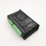
48V 30A 86mm 3 Phase BLDC Motor Driver With F R Control
|
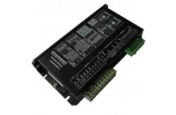
48V 30A 86mm brushelss dc motor speed driver, BLDC motor controller for 3 phase bldc motor with hall sensors
Description:
N Serires is speed driver with variable parameters and PI close-loop. The reference can be0∼5V analog voltage or 0∼100%PWM. Also it can be 0∼3kHz frequency by adding a F-V unit on PCB. Parameters can be set by DIP switches and potentiometers such as pole number, max speed, ramp time, loop filter time and peak current etc. Votage grades are 12,24,36,48VDC. Working current grades are 5,10,15A. Ambient temperarure grade are -10∼+45ºC,-40∼+65ºC
Features: ♦ Surface-mount technology and small size. ♦ 2-Quadrant PI close-loop control of speed with good linearity. ♦ Variable Parameter setting for different motors ♦ Control functions of F/R, enable, brake, speed reference and out put functions of speed pulse(PG), alarm. Over temperature protection. ♦ Three kinds of reference inputs: analog voltage, PWM, frequency. ♦ Suitable for 3 phase brushless DC motor with hall sensors ♦ Use of industrial grade chips.
Naming Rule:
BLSD 48 30 DC – 2Q – N - T P 48: Rated Voltage (VDC) 30: Peak Current Limit(A) DC: DC power input 2Q: 2-Quadrant driving mode N: N series (normal size and variable parameters) T: T=-40~+65 ºC Ta, unlabelled=-10~+45 ºC Ta P: P=0-3KHz pulse input at SV,unlabelled= 0-5V at SV
N Series 2Q BLDC Speed Driver With Fixed Parameters:
Notice: 1. Select peak current of driver : If the rated current Ir of motor
is presented, then Ip(A)≧2*Ir(A). If the rated output power of motor Pr(W) is presented, then Ip(A)≧4*Pr/Vr. Vr(V) is the rated voltage of motor. 2. Driving quadrant: The drivers are only used in Ⅰ& Ⅲ quadrant. 3. Frequency input: The F-V transfer module can be added to the driver for frequency control (0-3KHz/ TTL) at SV port. 4. Brake operation: When BK port is switched to low level, motor will stop running quickly by shorting windings through bottom MOSFETs. The motor speed at braking must not exceed Safe-Brake-Speed Ns (see the connection diagram). 5. Interference from leads:The Hall signals can be disturbed by switched current in windings leads when length is more than 500mm. Don’t intertwine them together. It is better to use shielded leads. 6. Motor Insulation: Hall sensors to Windings/Hall sensors to Motor Case/Windings to Motor Case Insulation Resistance > 500MOhm @ 500VDC Dielectric strength < 1mA@500VAC/50-60Hz/1 minute Typical Connections: |
||||||||||||||||||||||||||||||||||||||||||||||||||||||||||||||||||||||||||||||||||||||||||||||||||||||||||||||||||||||||||||||||||||||||||||||||||||||||||||||||||||||||||||||||||||||
| Product Tags: 48V three phase bldc motor driver 30A 3 Phase BLDC Motor Driver 30A three phase brushless dc motor Driver |
|
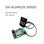
110V-220VAC BLDC Motor Driver 4A Current Hall or Sensorless Compatible and Hall phase sequence Self-adapting |
|
BLD-300B PWM Control Brushless DC Motor Driver 18-50V 300W With Closed Loop |
|
18-50V BLD-300B PWM Brushless DC Motor Driver With Open Loop |

|
High Speed Pwm 3 Phase BLDC Motor Driver Speed Controller |
|
2 Quadrant High Current 12V 3 Phase BLDC Motor Driver With Speed Showing Panel |
|
PI 2 Quadrant 720W Closed Loop Control Of Brushless Dc Motor With Hall Sensors |