
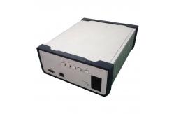
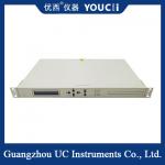
1x4 Desktop Optical Switch Working Wavelength 1260 ~ 1650nm
|
|
1x4 Desktop Optical Switch Working Wavelength 1260 ~ 1650nm 1x4 Desktop optical switch
Directions for use 1. Structure description 1.1 Front Panel Description Front Panel (1) LCD display: displays device address, current channel and
related information.
1.2 Rear Panel Description Rear panel (1) RJ45 Ethernet interface, RS-232 serial port: communication
interface for device monitoring data.
2. Device Connection Description 2.1 Internal optical path description Schematic diagram of the internal optical path of the 1 x 4 optical switch 2.2 Communication Interface connection Description (1) RS-232 interface
3. Panel operation instructions (1) Keyboard lock: The communication interface of the
channel device sends corresponding commands to set whether the keys
on the panel are allowed to use. See "Communication Protocol
Description" for details. When the panel key is locked, the
corresponding parameters cannot be set through the panel. ■ The procedure for allowing channel switch on the initial interface: ① press Enter to Enter the menu when you press the button to allow it to be used. ② Press "▲" or "▼" key to select "1. Channel lock setting"; ③ Press "Enter" to Enter. ④ Press "▲" or "▼" key to select "allow switch"; ⑤ Press "Enter" to confirm the completion. ⑥ During the whole process, press Esc to return to the previous step. ■ The procedure for locking a channel switch on an initial interface: (1) press Enter to Enter the menu when you allow it to be used. ② Press "▲" or "▼" key to select "1. Channel lock setting"; ③ Press "Enter" to Enter. ④ Press "▲" or "▼" key to select "lock switch"; ⑤ Press "Enter" to confirm the completion. ⑥ During the whole process, press Esc to return to the previous step. (3) Channel switching ■ When the initial interface allows a channel to switch, you can
press "▲" or "▼" to switch channels circularly. In the initial
interface lock channel switch, press "▲" or "▼" key can not switch
channels. ■ Press the① key to Enter the menu. ② Press "▲" or "▼" key to select "2. Channel mandatory selection"; ③ Press "Enter" to Enter. ④ Press the key "▲" or "▼" to select the "new channel"; ⑤ Press "Enter" to confirm the completion. ⑥ During the whole process, press Esc to return to the previous step. (4) Setting "Start channel" and "End channel" for automatic
scanning ■ Press the ① key to Enter the menu. ② Press "▲" or "▼" key to select "3. Scan
channel Settings"; ③ Press "Enter" to Enter. ④ Press the key "▲" or
"▼" to select the "starting channel"; ⑤ Press "Enter" to confirm
the completion. ⑥ Press "▲" or "▼" key to select "end channel"; ⑦
Press the "Enter" key to determine the completion. ⑧ During the
whole process, press Esc to return to the previous step. (5) Set the time of automatic scanning and start automatic scanning ■ Press the ① key to Enter the menu. ② Press "▲" or "▼" key to select "4. Automatic scan Settings"; ③ Press "Enter" to Enter. ④ Press the key "▲" or "▼" to select the "hour" of the scan interval; ⑤ Press the "Enter" key to confirm; ⑥ Press "▲" or "▼" key to select "minutes"; ⑦ press the "Enter" key to determine; ⑧ Press "▲" or "▼" key to select "second"; ⑨ Press Enter. If the time is not zero, automatic scan is started. ⑩ During the whole process, press Esc to return to the previous step. ■ During automatic scanning, there are three ways to stop scanning on the panel: (1) when the initial interface allows channel switching, press "▲" or "▼" to switch channels to stop scanning; ② Switch channels under "2. Channel mandatory Selection" to stop scanning. ③ In the menu "4. Automatic scan Settings" set the scanning time interval to "00 hours, 00 minutes, 00 seconds" to stop scanning. (6) Device address setting, which can be used to control multiple devices with different addresses in the case of tight serial port resources. ■ Press the ① key to Enter the menu. ② Press "▲" or "▼" key to select "5. Address setting"; ③ Press "Enter" to Enter. ④ Press "▲" or "▼" key to select "new address"; ⑤ Press "Enter" to confirm the completion. ⑥ During the whole process, press Esc to return to the previous step. (7) The setting of serial port baud rate can meet the Settings of different baud rates. The baud rate can be set as follows: 1200, 2400, 4800, 9600, 19200, 57600, 115200, usually set as 19200. (Note: The baud rate Settings take effect only after a restart.) ■ Press the①key to Enter the menu. ② Press "▲" or "▼" key to select "6. Baud rate setting"; ③ Press "Enter" to Enter. ④ Press "▲" or "▼" key to select "baud rate"; ⑤ Press "Enter" to confirm the completion. ⑥ During the whole process, press Esc to return to the previous step. (8) LCD backlight delay setting ■ Press the ①key to Enter the menu. ② Press "▲" or "▼" to select "7. LCD backlight"; ③ Press "Enter" to Enter. ④ Press the key "▲" or "▼" to select the delay time; ⑤ Press the "Enter" key to confirm; ⑥ During the whole process, press Esc to return to the previous step. (9) Error message prompt ■ Error 1 -- indicates a data overflow. .4. Description of upper computer monitoring The device can receive control signals from the computer through the RS-232 (or RS-485) interface on the front panel to realize automatic measurement or real-time monitoring (using the serial port monitoring system or serial port software), or remote monitoring through the Ethernet port. 4.1. Program control instruction |
| Product Tags: 1650nm Optical Switch 1x4 Desktop Optical Switch |

|
Edfa Module Optical Fiber Tester Erbium - Doped Fiber Amplifier |
|
Single Path Edfa Amplifier Long Distance Transmission 1528~1565nm |

|
1*8 Channel Desktop Optical Switch Automatic Scanning |

|
1x4 Desktop Optical Switch Small Insertion Loss Fast Switching Speed |

|
Multi - Channel Output Optical Switch Can Be Customized |

|
Four Channel Input And Eight Channel Output Optical Switch |