
Industrial Grade 2 Inch OLED Display Module 128x32 Graphic SPI I2C Interface
|
|
2" Inch 128x32 Graphic OLED display with SSD1309Z Parallel SPI I2C Interface COG with Flex for Soldering
OLED 2” inch Display, 128x32 OLED Display Description
The Organic Light-Emitting Diode (OLED) is a new generation technology, brighter and clearer images with more agile responding speed. This OLED 2" inch model no. SFOS200TW-12832W-01 OLED display is made of 128 x 32 dots individual mono color. This OLED module is lightweight, low power and small, there are different interfaces optional; it is default SPI, Parallel and I2C interface.
Pin Definition
Pin1, NC, No connection. Pin2, VCC, Power supply for panel driving voltage. Pin3, VCOMH, COM signal deselected voltage level. Pin4, IREF, This pin is the segment output current reference pin. Pin5~Pin12, D7-D0, These pins are bi-directional data bus connecting to the MCU data bus. Unused pins are recommended to tie LOW. When serial interface mode is selected, D0 will be the serial clock input: SCLK; D1 will be the serial data input: SDIN and D2 should be kept NC. When I2C mode is selected, D2, D1 should be tied together and serve as SDAout, SDAin in application and D0 is the serial clock input, SCL. Pin13, RD#, When interfacing to a 6800-series microprocessor, this pin will be used as the Enable (E)signal. Read/write operation is initiated when this pin is pulled HIGH and the chip is selected. When connecting to an 8080-microprocessor, this pin receives the Read (RD#) signal. Read operation is initiated when this pin is pulled LOW and the chip is selected. Serial interface, this pin must be connected to VSS. Pin14, WR#, This is read / write control input pin connecting to the MCU interface. When interfacing to a 6800-series microprocessor, this pin will be used as Read/Write (R/W#) selection input. Read mode will be carried out when this pin is pulled HIGH and write mode when LOW. When 8080 interface mode, this pin will be the Write (WR#) input. Data write operation is initiated when this pin is pulled LOW and the chip is selected. When serial interface, this pin must be connected to VSS. Pin15, D/C#, Data/Command data control pin.Low for command while high for data. Pin16, RES#, This pin is reset signal input. When the pin is LOW, initialization of the chip is executed.Keep this pin HIGH (i.e. connect to VDD) during normal operation. Pin17, CS#, The chip select pin. Active low. Pin18, NC, No connection. Pin19, BS2, MCU bus interface selection pins.Please refer to table followed for details of setting. Pin20, BS1, MCU bus interface selection pins.Please refer to table followed for details of setting. Pin21, VDD, Logic voltage supply for IC Pin22~Pin29, NC, No connection. Pin30, VSS, Ground. Pin31, NC, No connection.
OLED 2” inch Display, 128x32 OLED Display Description Drawing
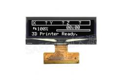
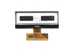
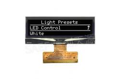
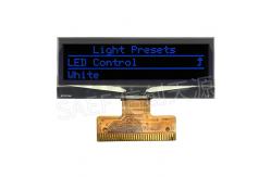
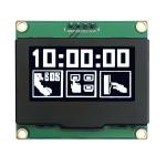
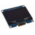
OLED 2” inch Display, 128x32 OLED Display Real Product Image
FACTORY AND FACILITIES
CONTACT
Welcome to inquire via ck@saef.com.cn
|
||||||||||||||||||||||||||||||||
| Product Tags: 2 Inch OLED Display Module OLED Display Module 128x32 I2C 2 inch oled display |
|
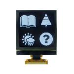
1.5 Inch OLED Module - 128x128 Monochrome White & Blue for IoT |
|
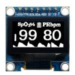
128x64 OLED Display - 0.96 Inch SSD1306 SPI for IoT and Arduino Projects | Best Price USA |
|
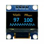
0.96 Inch OLED Display Module - 128x64 I2C, Yellow+Blue, 4-Pin Header Best Price USA |
|
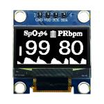
128x64 0.96-Inch OLED Display I2C Interface Compact Size 50 Lifetime Stock |
|
1.54-Inch I2C Interface SSD1309 Graphic OLED Display with Active Area 35.06 x 17.52 mm 128x64 Resolution |
|
1.54-Inch OLED Display Module 128x64 Resolution SPI Interface High Contrast Low Power Consumption |