
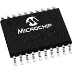
PIC16F1825T-I/ST PIC series Microcontroller IC Microchip FLASH 14-TSSOP
|

|
PIC16F1825T-I/ST PIC series Microcontroller IC Microchip FLASH 14-TSSOP
Related :PIC12(L)F1840 PIC12(L)F1822 PIC16(L)F1823 PIC16(L)F1824 PIC16(L)F1826 PIC16(L)F1827 PIC16(L)F1828 PIC16(L)F1829 PIC16(L)F1847
PIC series Microcontroller IC 8-Bit 32MHz 14KB (8K x 14) FLASH 14-TSSOP IC Specification:
Description(Datasheet): High-Performance RISC CPU • Only 49 Instructions to Learn: - All single-cycle instructions except branches • Operating Speed: - DC – 32 MHz oscillator/clock input - DC – 125 ns instruction cycle • Up to 16 Kbytes Linear Program Memory Addressing • Up to 1024 bytes Linear Data Memory Addressing • Interrupt Capability with Automatic Context Saving • 16-Level Deep Hardware Stack with Optional Overflow/Underflow Reset • Direct, Indirect and Relative Addressing modes: - Two full 16-bit File Select Registers (FSRs) - FSRs can read program and data memory Flexible Oscillator Structure • Precision 32 MHz Internal Oscillator Block: - Factory calibrated to ± 1%, typical - Software selectable frequencies range of 31 kHz to 32 MHz • 31 kHz Low-Power Internal Oscillator • Four Crystal modes up to 32 MHz • Three External Clock modes up to 32 MHz • 4x Phase Lock Loop (PLL) • Fail-Safe Clock Monitor: - Allows for safe shutdown if peripheral clock stops • Two-Speed Oscillator Start-Up • Reference Clock Module: - Programmable clock output frequency and duty cycle Special Microcontroller Features • 1.8V-5.5V Operation – PIC16F1825/9 • 1.8V-3.6V Operation – PIC16LF1825/9 • Self-Programmable under Software Control • Power-on Reset (POR), Power-up Timer (PWRT) and Oscillator Start-up Timer (OST) • Programmable Brown-out Reset (BOR) • Extended Watchdog Timer (WDT) • In-Circuit Serial Programming™ (ICSP™) via Two Pins • In-Circuit Debug (ICD) via Two Pins • Enhanced Low-Voltage Programming (LVP) • Programmable Code Protection • Power-Saving Sleep mode
Extreme Low-Power Management PIC16LF1825/9 with XLP • Sleep mode: 20 nA @ 1.8V, typical • Watchdog Timer: 300 nA @ 1.8V, typical • Timer1 Oscillator: 650 nA @ 32 kHz, 1.8V, typical • Operating Current: 48 µA/MHz @ 1.8V, typical Analog Features • Analog-to-Digital Converter (ADC) Module: - 10-bit resolution, up to 12 channels - Auto acquisition capability - Conversion available during Sleep • Analog Comparator Module: - Two rail-to-rail analog comparators - Power mode control - Software controllable hysteresis • Voltage Reference Module: - Fixed Voltage Reference (FVR) with 1.024V, 2.048V and 4.096V output levels - 5-bit rail-to-rail resistive DAC with positive and negative reference selection Peripheral Highlights • Up to 17 I/O Pins and 1 Input Only Pin: - High current sink/source 25 mA/25 mA - Programmable weak pull-ups - Programmable interrupt-on-change pins • Timer0: 8-Bit Timer/Counter with 8-Bit Prescaler • Enhanced Timer1: - 16-bit timer/counter with prescaler - External Gate Input mode - Dedicated, low-power 32 kHz oscillator driver • Three Timer2-types: 8-Bit Timer/Counter with 8-Bit Period Register, Prescaler and Postscaler • Two Capture, Compare, PWM (CCP) Modules • Two Enhanced CCP (ECCP) Modules: - Software selectable time bases - Auto-shutdown and auto-restart - PWM steering • Up to Two Master Synchronous Serial Port (MSSP) with SPI and I2CTM with: - 7-bit address masking - SMBus/PMBusTM compatibility • Enhanced Universal Synchronous Asynchronous Receiver Transmitter (EUSART) Module • mTouch™ Sensing Oscillator Module: - Up to 12 input channels
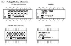
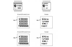
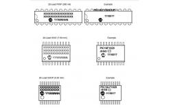
14/20-Pin Flash Microcontrollers with XLP Technology microcontroller IC Marking information:
Environmental & Export Classifications
|
|
BCM54616SC0IFBG |
|
KSZ8041FTL-TR |
|
ATSAML10D16A-MU ATSAML10D16 Microcontroller Microchip MCU IC |

|
Microchip CM4 QFN48 256KFlash Tray USB IC Integrated Circuits ATSAMD51 |
|
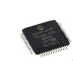
PIC24FJ128GB106-I/PT PIC24FJ128GB106 Microcontroller MCU IC Microchip Flash 8Bit |
|
PIC16F18346-I/SO Microchip Flash 8Bit Microcontroller MCU IC SOIC20 |