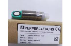
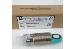
Ultrasonic sensor UB800-18GM40-U-V1 < Short design, 40 mm <
Function indicators visible from all directions < Analog output
0 ... 10 V < Measuring window adjustable < Program input <
Temperature compensation Single head system Dimensions 10 M18 x 1
M12 x 1 4 24 24.5 LED 39.2 50.2 Technical Data General
specifications Sensing range 50 ... 800 mm Adjustment range 70 ...
800 mm Dead band 0 ... 50 mm Standard target plate 100 mm x 100 mm
Transducer frequency approx. 255 kHz Response delay approx. 100 ms
Indicators/operating means LED green Power on 1 Release date:
2023-11-- 07 Date of Release date: 2023-11-07 Date of issue:
2023-11-07 Filename: 205336_eng.pdf Group Germany: +49 621 776 1111
Refer to "General Notes Relating to Product Information". USA: +1
330 486 0001 Singapore: +65 6779 9091 www.pepperl-fuchs.com
fa-info@us.pepperl-fuchs.com fa-info@de.pepperl-fuchs.com
fa-info@sg.pepperl-fuchs.com Technical Data LED yellow solid
yellow: object in the evaluation range yellow, flashing: program
function, object detected LED red solid red: Error red, flashing:
program function, object not detected Electrical specifications
Operating voltage UB 15 ... 30 V DC , ripple 10 %SS No-load supply
current I0 ≤ 20 mA Input Input type 1 program input lower
evaluation limit A1: -UB ... +1 V, upper evaluation limit A2: +4 V
... +UB input impedance: > 4.7 kΩ, pulse duration: ≥ 1 s Output
Output type 1 analog output 0 ... 10 V Default setting evaluation
limit A1: 70 mm evaluation limit A2: 800 mm Resolution 0.4 mm at
max. sensing range Deviation of the characteristic curve ± 1 % of
full-scale value Repeat accuracy ± 0.5 % of full-scale value Load
impedance > 1 kOhm Temperature influence ± 1.5 % of full-scale
value Compliance with standards and directives Standard conformity
Standards EN IEC 60947-5-2:2020 IEC 60947-5-2:2019 EN
60947-5-7:2003 IEC 60947-5-7:2003 Approvals and certificates UL
approval cULus Listed, Class 2 Power Source CCC approval CCC
approval / marking not required for products rated ≤36 V Ambient
conditions Ambient temperature -25 ... 70 °C (-13 ... 158 °F)
Storage temperature -40 ... 85 °C (-40 ... 185 °F) Mechanical
specifications Connection type Connector plug M12 x 1 , 4-pin
Housing length 40 mm Housing diameter 18 mm Degree of protection
IP67 Material Housing brass, nickel-plated Transducer epoxy
resin/hollow glass sphere mixture; foam polyurethane, cover PBT
Mass 25 g Connection 3 (BU) 1 (BN) 2 (WH) 4 (BK) U + UB Teach input
Analogue output - UB Core colours in accordance with EN 60947-5-2.
Standard symbol/Connections: (version U) Ultrasonic sensor
UB800-18GM40-U-V1 Release date: 2023-11-07 Date of issue:
2023-11-07 Filename: 205336_eng.pdf 2 Group Germany: +49 621 776
1111 Refer to "General Notes Relating to Product Information". USA:
+1 330 486 0001 Singapore: +65 6779 9091 www.pepperl-fuchs.com
fa-info@us.pepperl-fuchs.com fa-info@de.pepperl-fuchs.com
fa-info@sg.pepperl-fuchs.com Connection Assignment 1 3 2 4 1 BN 2
WH 3 BU 4 BK Wire colors in accordance with EN 60947-5-2 (brown)
(white) (blue) (black) Characteristic Curve Characteristic response
curve Distance X [mm] Distance Y [mm] Curve 1: flat surface 100 mm
x 100 mm Curve 2: round bar, Ø 25 mm 0 200 400 600 800 1000 1200
1400 200 150 100 50 0 -50 -100 -150 -200 2 1 X Y Programming the
analog output mode Rising ramp A1 < A2: Falling ramp A2 < A1:
object range A1 -> ∞, A2 -> ∞: Detection of object presence
Object detected: 10 V No object detected: 0 V A1 A2 A2 A1
Programming The sensor features a programmable analog output with
two programmable evaluation boundaries. Programming the evaluation
boundaries and the operating mode is done by applying the supply
voltage -UB or +UB to the Teach-In input. The supply voltage must
be applied to the Teach-In input for at least 1 s. LEDs indicate
whether the sensor has recognized the target during the programming
procedure. Note: Evaluation boundaries may only be specified
directly after Power on. A time lock secures the adjusted switching
points against unintended modification 5 minutes after Power on. To
modify the evaluation boundaries later, the user may specify the
desired values only after a new Power On. Note: If a programming
adapter UB-PROG2 is used for the programming procedure, button A1
is assigned to -UB and button A2 is assigned to +UB. Ultrasonic
sensor UB800-18GM40-U-V1 Release date: 2023-11-07 Date of issue:
2023-11-07 Filename: 205336_eng.pdf 3 Group Germany: +49 621 776
1111 Refer to "General Notes Relating to Product Information". USA:
+1 330 486 0001 Singapore: +65 6779 9091 www.pepperl-fuchs.com
fa-info@us.pepperl-fuchs.com fa-info@de.pepperl-fuchs.com
fa-info@sg.pepperl-fuchs.com Programming Programming the analog
output Rising ramp 1. Place the target at the near end of the
desired evaluation range 2. Program the evaluation boundary by
applying -UB to the Teach-In input (yellow LED flashes) 3.
Disconnect the Teach-In input from -UB to save the evaluation
boundary 4. Place the target at the far end of the desired
evaluation range 5. Program the evaluation boundary by applying +UB
to the Teach-In input (yellow LED flashes) 6. Disconnect the
Teach-In input from +UB to save the evaluation boundary Falling
ramp 1. Place the target at the far end of the desired evaluation
range 2. Program the evaluation boundary by applying -UB to the
Teach-In input (yellow LED flashes) 3. Disconnect the Teach-In
input from -UB to save the evaluation boundary 4. Place the target
at the near end of the desired evaluation range 5. Program the
evaluation boundary by applying +UB to the Teach-In input (yellow
LED flashes) 6. Disconnect the Teach-In input from +UB to save the
evaluation boundary Ultrasonic sensor UB800-18GM40-U-V1 Release
date: 2023-11-07 Date of issue: 2023-11-07 Filename: 205336_eng.pdf
4 Group Germany: +49 621 776 111