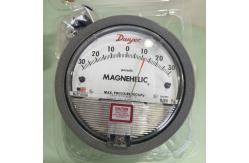
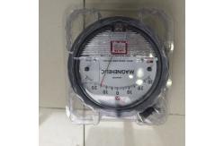
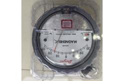
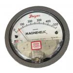
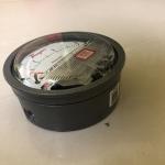
Select the Dwyer® Magnehelic® gage for high accuracy — guaranteed
within 2% of full-scale — and for the wide choice of 81 models
available to suit your needs precisely. Using Dwyer's simple,
frictionless Magnehelic® gage movement, it quickly indicates low
air or noncorrosive gas pressures — either positive, negative
(vacuum) or differential. The design resists shock, vibration and
over-pressures. No manometer fluid to evaporate, freeze or cause
toxic or leveling problems. It's inexpensive, too. The Magnehelic®
gage is the industry standard to measure fan and blower pressures,
filter resistance, air velocity, furnace draft, pressure drop
across orifice plates, liquid levels with bubbler systems and
pressures in fluid amplifier or fluidic systems. It also checks
gas-air ratio controls and automatic valves, and monitors blood and
respiratory pressures in medical care equipment. Mounting A single
case size is used for most models of Magnehelic® gages. They can be
flush or surface mounted with standard hardware supplied. Although
calibrated for vertical position, many ranges above 1˝ may be used
at any angle by simply re-zeroing. However, for maximum accuracy,
they must be calibrated in the same position in which they are
used. These characteristics make Magnehelic® gages ideal for both
stationary and portable applications. A 4-9/16˝ hole is required
for flush panel mounting. Complete mounting and connection
fittings, plus instructions, are furnished with each instrument.
See pages 6 and 7 for more information on mounting accessories.
SPECIFICATIONS Service: Air and non-combustible, compatible gases
(natural gas option available). Note: May be used with hydrogen.
Order a Buna-N diaphragm. Pressures must be less than 35 psi.
Wetted Materials: Consult factory. Housing: Die cast aluminum case
and bezel, with acrylic cover. Exterior finish is coated gray to
withstand 168 hour salt spray corrosion test. Accuracy: ±2% of FS
(±3% on - 0, -100 Pa, -125 Pa, 10MM and ±4% on - 00, -60 Pa, -6MM
ranges), throughout range at 70°F (21.1°C). Pressure Limits: -20 in
Hg to 15 psig† (-0.677 to 1.034 bar); MP option: 35 psig (2.41
bar); HP option: 80 psig (5.52 bar). Overpressure: Relief plug
opens at approximately 25 psig (1.72 bar), standard gages only. See
Overpressure Protection Note on next page. Temperature Limits: 20
to 140°F* (-6.67 to 60°C). -20°F (-28°C) with low temperature
option. Size: 4˝ (101.6 mm) diameter dial face. Mounting
Orientation: Diaphragm in vertical position. Consult factory for
other position orientations. Process Connections: 1/8˝ female NPT
duplicate high and low pressure taps - one pair side and one pair
back. Weight: 1 lb 2 oz (510 g), MP & HP 2 lb 2 oz (963 g).
Standard Accessories: Two 1/8˝ NPT plugs for duplicate pressure
taps, two 1/8˝ pipe thread to rubber tubing adapter, and three
flush mounting adapters with screws. (Mounting and snap ring
retainer substituted for three adapters in MP & HP gage
accessories.) Agency Approval: RoHS. Note: -SP models not RoHS
approved. 1/8 FEMALE NPT HIGH PRESSURE CONNECTION 1-3/4 (44.45) 1/2
(12.70) 1/8 FEMALE NPT LOW PRESSURE CONNECTION 11/16 (17.46) 17/32
(13.49) ø4-3/4 (120.65) PANEL CUTOUT ø5 (127) ø4-47/64 (120.27)
3/16 (4.76) 2-17/32 (64.29) 15/32 (11.91) ø4-1/2 (114.3) 1-1/4
(31.75) ø5-1/2 (139.70) MOUNTING RING RUBBER PRESSURE RELIEF PLUG
WILL UNSEAT ITSELF WHEN GAGE IS OVERPRESSURIZED (3) 6-32 X 3/16
(4.76) DEEP HOLES EQUALLY SPACED ON A Ø4-1/8 (104.78) BOLT CIRCLE
FOR PANEL MOUNTING 1/8 FEMALE NPT HIGH PRESSURE CONNECTION 1-3/4
(44.45) 1/2 (12.70) 1/8 FEMALE NPT LOW PRESSURE CONNECTION 11/16
(17.46) 15/32 (11.91) 1-11/16 (42.86) Ø4-1/2 (114.3) 1-1/4 (31.75)
17/32 (13.49) .025 (.64) SPACE CREATED BY 3 SPACER PADS WHEN
SURFACE MOUNTED. DO NOT OBSTRUCT. PROVIDES PATH FOR RELIEF OF
OVERPRESSURE. 1/8 FEMALE NPT HIGH PRESSURE CONNECTION 1/8 FEMALE
NPT LOW PRESSURE CONNECTION 7/16 (11.11) Ø4-3/4 (120.65) Flush,
Surface or Pipe Mounted Enclosure Mounted ACCESSORIES †For
applications with high cycle rate within gage total pressure
rating, next higher rating is recommended. See Medium and High
pressure options at lower left. A-605B Air Filter Gage Accessory
Kit, Air filter kit with two plastic open/close valves, two 4˝
steel static tips, plastic tubing and mounting flange . . . . . . .
. .26.00 A-605C Air Filter Gage Accessory Kit, Air filter kit with
two plastic open/close valves, two plastic static tips, plastic
tubing and mounting flange . . . . . . . . . .21.00 Model A-432
Portable Kit Combine carrying case with any Magnehelic® gage of
standard range, except high pressure connection. Includes 9 ft (2.7
m) of 3/16˝ ID rubber tubing, standhang bracket and terminal tube
with holder . . . . . . . . . . . . . . . . . . . . . . . . . . . .
. . . . . . . . . . .$48.00 Model A-605 Air Filter Gage Accessory
Kit Adapts any standard Magnehelic® gage for use as an air filter
gage. Includes aluminum surface mounting bracket with screws, two 5
ft (1.5 m) lengths of 1/4˝ aluminum tubing two static pressure tips
and two molded plastic vent valves, integral compression fittings
on both tips and valves . . . . . . . . . . . . .35.00 004_Layout 2
7/16/12 10:56 AM Page 4 5 Differential Pressure Gages Series
PRESSURE 2000 Magnehelic® Gage Models & Ranges Dual Scale Air
Velocity Units For use with pitot tube Zero Center Ranges
2300-6MM†•• 2300-10MM†• 2300-20MM†• Model 2000-00AV†•• 2000-0AV†•
2001AV 2002AV 2005AV 2010AV Model 2000-60NPA†•• 2000-60PA†••
2000-100PA†• 2000-125PA†• 2000-250PA 2000-300PA 2000-500PA
2000-750PA 2000-1000PA Model 2000-6MM†•• 2000-10MM†• 2000-15MM
2000-25MM 2000-30MM 2000-50MM 2000-80MM 2000-100MM 2000-125MM
2000-150MM 2000-200MM 2000-250MM 2000-300MM Model 2000-0.5KPA
2000-1KPA 2000-1.5KPA 2000-2KPA 2000-2.5KPA 2000-3KPA 2000-4KPA
2000-5KPA 2000-8KPA 2000-10KPA 2000-15KPA 2000-20KPA 2000-25KPA
2000-30KPA 2300-1KPA 2300-2KPA 2300-2.5KPA 2300-3KPA Model
2300-60PA†•• 2300-100PA†• 2300-120PA 2300-200PA 2300-250PA
2300-300PA 2300-500PA 2300-1000PA Dual Scale English/Metric Models
Model 2000-00D†•• 2000-0D†• 2001D 2002D 2003D 2004D 2005D 2006D
2008D 2010D 2015D 2020D 2025D 2050D 2060D Range, in w.c. 0-.25
0-0.5 0-1.0 0-2.0 0-3.0 0-4.0 0-5.0 0-6.0 0-8.0 0-10 0-15 0-20 0-25
0-50 0-60 Zero Center Ranges Zero Center Ranges 2300-00†•• 2300-0†•
2301 2302 2304 2310 2320 2330 Model 2201 2202 2203 2204 2205 2210*
2215* 2220* 2230** Model 2000-15CM 2000-20CM 2000-25CM 2000-50CM
2000-80CM 2000-100CM 2000-150CM 2000-200CM 2000-250CM 2000-300CM
2300-4CM 2300-10CM 2300-30CM Model 2000-00N†•• 2000-00†•• 2000-0†•
2001 2002 2003 2004 2005 2006 2008 2010 2012 2015 2020 2025 2030
2040 2050 2060 2080 2100 2120 2150 2160 2180* 2250* †These ranges
calibrated for vertical scale position. • Accuracy +/-3% • •
Accuracy +/-4% *MP option standard **HP option standard Zero Center
Ranges Zero Center Ranges O-ring seal for cover assures pressure
integrity of case. OVERPRESSURE PROTECTION Blowout plug is
comprised of a rubber plug on the rear which functions as a relief
valve by unseating and venting the gage interior when over pressure
reaches approximately 25 psig (1.7 bar). To provide a free path for
pressure relief, there are four spacer pads which maintain 0.023˝
clearance when gage is surface mounted. Do not obstruct the gap
created by these pads. The blowout plug is not used on models above
180˝ of water pressure, medium or high pressure models, or on gages
which require an elastomer other than silicone for the diaphragm.
The blowout plug should not be used as a system overpressure
control. High supply pressures may still cause the gage to fail due
to over pressurization, resulting in property damage or serious
injury. Good engineering practices should be utilized to prevent
your system from exceeding the ratings or any component. Die cast
aluminum case is precision made and iridite-dipped to withstand 168
hour salt spray corrosion test. Exterior finished in baked dark
gray hammerloid. One case size is used for all standard pressure
options, and for both surface and flush mounting. Silicone rubber
diaphragm with integrally molded O-ring is supported by front and
rear plates. It is locked and sealed in position with a sealing
plate and retaining ring. Diaphragm motion is restricted to prevent
damage due to overpressures. Samarium Cobalt magnet mounted at one
end of range spring rotates helix without mechanical linkages.
Bezel provides flange for flush mounting in panel. Clear plastic
face is highly resistant to breakage. Provides undistorted viewing
of pointer and scale. Precision litho-printed scale is accurate and
easy to read. Red tipped pointer of heat treated aluminum tubing is
easy to see. It is rigidly mounted on the helix shaft. Pointer
stops of molded rubber prevent pointer over-travel without damage.
“Wishbone” assembly provides mounting for helix, helix bearings and
pointer shaft. Jeweled bearings are shock-resistant mounted;
provide virtually friction-free motion for helix. Motion damped
with high viscosity silicone fluid. Zero adjustment screw is
conveniently located in the plastic cover, and is accessible
without removing cover. O-ring seal provides pressure tightness.
Helix is precision made from an alloy of high magnetic
permeability. Mounted in jeweled bearings, it turns freely,
following the magnetic field to move the pointer across the scale.
Calibrated range spring is flat spring steel. Small amplitude of
motion assures consistency and long life. It reacts to pressure on
diaphragm. Live length adjustable for calibration. VELOCITY AND
VOLUMETRIC FLOW UNITS Scales are available on the Magnehelic® that
read in velocity units (FPM, m/s) or volumetric flow units (SCFM,
m3/s, m3/h). Stocked velocity units with dual range scales in
inches w.c. and feet per minute are shown above. For other ranges
contact the factory. When ordering volumetric flow scales please
specify the maximum flow rate and its corresponding pressure.
Example: 0.5 in w.c. = 16,000 CFM. CALL TO ORDER | 800/872-9141
Range in W.C./ Velocity F.P.M. 0-.25/ 300-2000 0-.50/ 500-2800
0-1.0/ 500-4000 0-2.0/ 1000-5600 0-5.0/ 2000-8800 0-10/ 2000-12500
Price $98.00 88.50 67.95 67.95 67.95 67.95 .5-0-.5 1-0-1
1.25-0-1.25 1.5-0-1.5 $74.00 74.00 74.00 74.00 Range, kPa 0-0.5 0-1
0-1.5 0-2 0-2.5 0-3 0-4 0-5 0-8 0-10 0