Key features- Pressure Source and mA Measurement to calibrate pressure devices
- Built-in pump for sourcing pressure to 300 PSI
- Easy-to-clean, field-serviceable, integrated pressure pump
- Built-in switch test for calibrating pressure switches
- Extend pressure capabilities by using Fluke 750P pressure modules
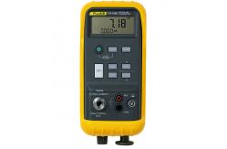
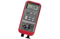
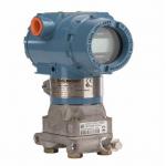
- Pressure Calibrator Introduction The Fluke 718 Series Pressure
Calibrators do the following: • Calibrate P/I (pressure to current)
transmitters • Measure pressure via a 1/8-inch NPT pressure fitting
and an internal pressure sensor or via a Fluke 700 Series Pressure
Module • Source pressure • Measure current up to 24 mA •
Simultaneously display pressure and current measurements. • Supply
loop voltage • Calculate mA percentage in Percent Mode • Calculate
mA error % in Percent Error Mode The 718 Pressure Calibrators
(hereafter, “the Calibrator”) include: • 718 1G • 718 30G • 718
100G • 718 300G The Calibrator makes 5-digit pressure readings in
the following units: psi, inH2O at 4 °C, inH2O at 20 °C, kPa, cmH2O
at 4 °C, cmH2O at 20 °C, bar, mbar, kg/cm2 , inHg, and mmHg.
Pressure sensor specifications are as listed under “Pressure Sensor
Input”. The Calibrator measures pressure sensor inputs in the units
shown in Table 1. For pressure modules, full scale readings for all
pressure ranges can be made in psi, kPa, and inHg units. To avoid
display overflow, full scale readings are limited to 1000 psi in
cmH2O, mbar, and mmHg units, and 3000 psi in inH2 O units.
Pressures of at least 15 psi must be measured for meaningful
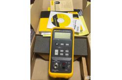
readings in bar and kg/cm2 units. Your Calibrator is supplied with
a holster, two installed 9 V alkaline batteries, one set of TL75
test leads, one set of AC70A alligator clips, one 700-ILF In-Line
Filter (to protect the pump), a Product Overview Manual, and a
CD-Rom. If the Calibrator is damaged or something is missing,
contact the place of purchase immediately. Contact your Fluke
distributor for information about accessories. See 718 Series Users
Manual 2 “How to Contact Fluke.” To order replacement parts or
spares, see “Parts and Accessories.” Table 1. Input Units Displayed
Pressure Units psi inH2O at 4°C inH2O at 20°C cmH2O at 4°C cmH2O at
20°C bar mbar kPa inHg mmHg kg/cm2 Safety Information Use the
Calibrator only as specified in this Users Manual, otherwise the
protection provided by the Calibrator may be impaired. A Warning
identifies conditions and actions that pose hazard(s) to the user;
a Caution identifies conditions and actions that may damage the
Calibrator or the equipment under test. Pressure Calibrator Safety
Information 3 Table 2. Safety Information XW Warning To avoid
possible electric shock or personal injury: • Never apply more than
30 V between the mA terminals, or between either of the mA
terminals and earth ground. • Do not use the Calibrator to make
measurements in a CAT II, CAT III, or a CAT IV environment. CAT I
equipment is designed to protect against transient from
high-voltage, low-energy sources, such as electronic circuits or a
copy machine • Remove the test leads from the Calibrator before you
open the battery door. • Make sure the battery door is closed and
latched before you operate the Calibrator. • Do not operate the
Calibrator if it is damaged. • Do not operate the Calibrator around
explosive gas, vapor, or dust. • When using probes, keep fingers
behind the finger guards on the probes. • Use only two 9 V
batteries, properly installed in the Calibrator case, to power the
Calibrator. • Follow all equipment safety procedures. • Turn off
circuit power before connecting the Calibrator mA and COM terminals
in the circuit. Place Calibrator in series with the circuit. • When
servicing the Calibrator, use only specified replacement parts.
|