
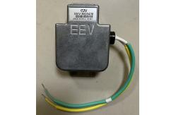
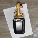
25kW E2V Control Valves X-Band Magnetron For Marine Radar
|


|
E2V Technologies EEV MG5436 25kW X-Band Magnetron Marine Radar
DescriptionElectrical
Mechanical Magnet integral A minimum clearance of 25 mm must be maintained
between the magnetron and any magnetic materials. Compact, rugged, lightweight, fixed frequency pulse magnetron, designed for marine radar applications.
specification
NOTES1. For optimum performance a value of 6.3 V is recommended. However, this magnetron will work satisfactorily within the specified limits. The magnetron heater must be protected against arcing by the use of a minimum capacitance of 4000 pF shunted across the heater directly at the input terminals; in some cases a capacitance as high as 2 mF may be necessary depending on the equipment design. For further details see the Magnetron Preamble.
2. Measured with heater voltage of 6.3 V and no anode input power, the heater current limits are 0.5 A minimum, 0.6 A maximum.
3. For ambient temperatures above 0 8C. For ambient temperatures between 0 and 755 8C, cathode pre-heating time is 90 seconds minimum.
4. Design test only. The maximum frequency change with anode temperature change (after warming) is 70.25 MHz/8C.
5. The various parameters are related by the following formula: Pi = iapk x vapk x Du where Pi = mean input power in watts iapk = peak anode current in amperes vapk = peak anode voltage in volts and Du = duty cycle. For mean pulse input power greater than 45 W the heater voltage must be reduced within 3 seconds after the application of HT according to the following schedule: Vh = 0.08 (110 7 Pi) volts where Pi = mean input power in watts.
6. Defined as the steepest tangent to the leading edge of the voltage pulse above 80% amplitude. Any capacitance in the viewing system must not exceed 6.0 pF.
7. The maximum rate of rise of voltage for stable operation depends upon detailed characteristics of the applied pulse and the pulser design. The specified maximum rating applies to typical hard tube pulsers. For minimum starting jitter and optimum operation, the recommended rate of rise of voltage for most line type pulsers is from 60 to 90 kV/ms.
8. Tolerance + 40%.
9. Other frequency ranges can be supplied on request.
10. With the magnetron operating into a VSWR of 1.15:1 over a peak anode current range of 6.0 to 10 A. Pulses are defined as missing when the RF energy level is less than 70% of the normal energy level in a 0.5% frequency range. Missing pulses are expressed as a percentage of the number of input pulses applied during a two minute period of observation.
11. Measurements taken ‘as read’ using suitably calibrated equipment.
|
||||||||||||||||||
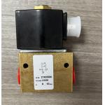
| Product Tags: Marine Radar Flow Control Valve Magnetron Hydraulic Control Valve E2V Hydraulic Motor Control Valve |
|
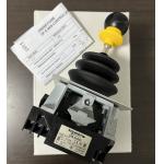
XKBA34229 XKBA32330 Schneider Joystick Controller Brand New |
|
Good Price ASCO Solenoid Valve Original ASCO, MODEL: 13100156 3/2 WAYS, SIZE: 1/4" 230/50 HZ |
|
Norgren 2102500000000000 Direct Solenoid Actuated Poppet Valve ODM Customized Assistance |

|
New Norgren 2/2 Direct Solenoid Actuated Poppet Valve 2102500 |
|
Original Rotork YTC YT-530D21 Snap Acting Relay Rugged and Reliable Design Specically Designed for Valve Actuation |
|
Samson 3730-3 Electro Pneumatic Positioner 3730-3000000040000000 0.01 Valve Positioner |