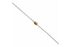
A104K15X7RF5TAA Multilayer Ceramic Capacitors CAP CER 0.1UF 50V X7R Axial Leaded
|
|
Ceramic Capacitors A104K15X7RF5TAA CAP CER 0.1UF 50V X7R AXIAL / Axial Leaded Multilayer Ceramic Capacitors for General
MARKING Marking indicates capacitance value and tolerance in accordance with “EIA 198” and voltage marks.
OPERATING TEMPERATURE RANGE C0G, X7R: - 55 °C to + 125 °C Y5V: - 30 °C to + 85 °C
TEMPERATURE CHARACTERISTICS Class 1: C0G Class 2: X7R Class 3: Y5V
SECTIONAL SPECIFICATIONS Climatic category (acc. to EN 60058-1) Class 1 and 2: 55/125/21 Class 3: 30/85/21
APPROVALS EIA 198 IEC 60384-9
DESIGN • The capacitors consist of a general purpose MLCC • The lead wires are 0.5 mm and are made of 100 % tinned copper clad steel wire • Coating is made of yellow colored flame retardant epoxy resin in accordance with UL 94 V-0
CAPACITANCE RANGE 10 pF to 1 μF
TOLERANCE ON CAPACITANCE ± 5 %, ± 10 %, ± 20 %, + 80 %/- 20 %
RATED VOLTAGE 50 VDC, 100 VDC, 200 VDC, 500 VDC
TEST VOLTAGE • 50 VDC and 100 VDC: 250 % of rated voltage • 200 VDC: 150 % of rated voltage + 100 VDC • 500 VDC: 130 % of rated voltage + 100 VDC
INSULATION RESISTANCE AT 500 VDC • 50 VDC and 100 VDC: 100 G or 1000 F whichever is less at rated voltage within 2 min of charging • 200 VDC and 500 VDC: 10 G or 100 F whichever is less at rated voltage within 2 min of charging
DISSIPATION FACTOR Class 1: 0.1 % max. when C 30 pF (at 1 MHz; 1 V where C 1000 pF, and at 1 kHz; 1 V where C > 1000 pF) For C < 30 pF: DF = 100/(400 + 20 x C) DF = Disspation factor in %; C = Capacitance value in pF Class 2: 2.5 % max. (at 1 kHz; 1 V) Class 3: 5 % max. (at 1 kHz; 1 V) |
||||||||||||||||||||||||||||||||||||
| Product Tags: 50V Multilayer Ceramic Capacitors 0.1UF Multilayer Ceramic Capacitors Ceramic Axial Leaded Capacitors |