
Communication protocol : Rs485,CAN, LAN
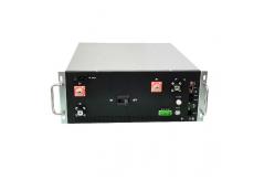
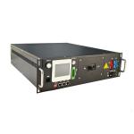
* 4U standard 19inch case
* Efficient, stable and reliable
* size:W485*H180*D550mm
Hunan GCE Technology Co.,Ltd
City: changsha
Province/State:hunan
Country/Region:china
Tel:86-731-86187065
Contact Person:
|
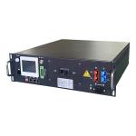
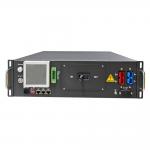
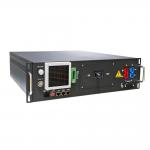
GCE 1500V ESS High voltage lithium battery management system BMS quality long life solar energy storage systemProduct system overview
Description
BMSs can also perform other functions such as cell balancing, which helps to ensure that all cells in a battery pack are charged to the same level, and fault detection, which alerts the user to any issues such as short circuits or open circuits in the battery system. BMSs are essential for ensuring the safe and reliable operation of battery systems in a wide range of applications. They help to prevent safety hazards such as fires or explosions that can result from overcharging or overheating, and can also help to extend the lifespan of the battery by preventing damage from overcharging or overdischarging.
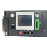
Application scenarios◎ PV power plant storage ◎ Island off-grid energy storage ◎ optical storage charge integration applications ◎ UPS power supply Specification RBMS Interface Description
1024V 200Amp 4U RBMS Communication protocol : Rs485,CAN, LAN * 4U standard 19inch case * Efficient, stable and reliable * size:W485*H180*D550mm Accessories8S-24S BMU(Slave)8S-24S BMU has 8pcs of tempreture sensors, Fan voltage 48V(17S-24S
12V), voltage detection range 0-5V,12V power supply,consumption
less 20mA, CAN2.0 B communication Wire harness-Signal acquisition wire18 Pin+20Pin wire, standard length is 600mm,900mm,1200mmtempreture
sensor. wire: standard length is 600mm,900mm,1200mm Fan wire: 600mm Wire harness-communication wireCommunication wire is connecting from master BMS to each BMU with
cascade connection, the last port is for terminal resistance.wire: standard length is 180mm,300mm,600mm |
| Product Tags: 1500V ESS Solar Energy Storage System 1500V BMS Solar Energy Storage System |
|
Voltage Range 120V-600V High Voltage BMS With CAN Communication Port |
|
RS485 CAN Communication Battery Management System For 120V-600V Lithium Ion Battery |
|
Standard 19 Inch Rack Installation High Voltage BMS With NMC Battery Type |
|
Power Consumption ≤15W Lithium Ion Battery Management System With CAN / RS485 Interface |
|
Lifepo4 Battery BMS Lithium BMS High Voltage BMS 120V-600V Battery Management System In Solar Energy Storage |
|
High Voltage BMS For Effective Power Control Voltage Range 120V-600V Lifepo4 Lithium Solar BESS UPS BMS |