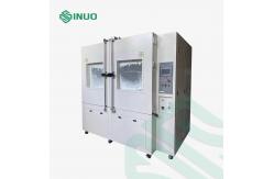
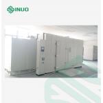
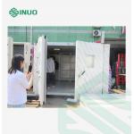
IEC60529 IP5/6X EV Charge Station Walk-In Sand & Dust Test
Chamber Complied Standards & Clauses
IEC60529:2013 "Degrees of protection provided by enclosure (IP
code)" IP5X and IP6X. Equipment Overview
This equipment is suitable for testing electronic and electrical
products, automobile and motorcycle accessories, and seals in sandy
and dusty environments to prevent sand and dust from entering the
seals and casings. Test the performance of electronic and
electrical products, automobile and motorcycle parts, and seals in
use, storage, and transportation in sandy and dusty environments.
The purpose of the testing is to determine the possible harmful
effects that airflow-borne particles may have on electrical
products. The test can be used to simulate open-air sand and dust
air environmental conditions caused by natural environments or
man-made disturbances such as vehicle movement. Technical Parameters
| Volume and dimensions | | Effective volume of inner chamber | About 24 cubic meters | | Inner chamber dimensions | 2000*3000*4000mm (W*D*H) | | Outer chamber dimensions | About 3000*3800*5000 mm(W*D*H) (Including trench size) | | Trench size | The trench size is W3300*D3700*H1200. Please see the attached
picture for details (including 500mm aisle size) | | Test sample specifications | Charging stations, electrical cabinets, energy storage cabinets The size range is not larger than: W (260~2000) × D (200~1000) × H
(1000~3000) mm | | Function parameters | | Working room temperature | RT+10℃~+70℃ | | Working humidity | ≤75%R.H | | Product vacuum degree | ≤60KPa | | Dust composition | Talcum powder | | Composition of dust particles | Dry talcum powder that can pass through a square hole sieve with a
mesh size of 75µm and a wire mesh diameter of 50µm | | Dust concentration | 2~4kg/m3 | | Air flow meter | Mechanical type | | Airflow speed | Not more than 2m/s | | Time of control | Dust blowing control cycle: 1s ~ 99h (adjustable), test time
timing: 1s ~ 99h (adjustable), vibration time: 1S ~ 99H
(adjustable) | | Metal mesh | Nominal line length: ≥50μm, standard spacing between lines: ≥75μm. | | Sand and dust air circulation device | Circulation air ducts and high-power mixed-flow ventilators have an
air extraction volume of 80 times the tested shell volume, and the
air extraction speed does not exceed 60 times the shell volume per
hour. And the speed of the air flow can make the dust evenly
distributed in the test chamber. The airflow in the test chamber is
mainly top-down vertical airflow rather than laminar flow. The
pressure gauge has a calibration interface. | | Load-bearing capacity of cargo platform | Not less than 500kg | | Dust drying system | The equipment is equipped with a dust drying heating device, and
there is a heating button on the controller control screen. When
the dust is found to be a little moist during the test, you can
turn on the heating button in the control screen and start the dust
heating device to dry the dust. The button can be turned off after
the dust has dried. The drying process will not affect the test
process, effectively ensuring the dust concentration in the test
chamber and ensuring the accuracy of the test data. | | How to change dust | Use a manual vacuum cleaner to replace the dust manually, and the
dust can be easily replaced at any time |
1. The equipment is a walk-in structure with spliced warehouse
boards. There is a funnel in each of the four corners. The middle
flat adopts a dust brush structure. The side-through dust brush
structure brushes dust into the funnels on both sides. 2. There is a rotating sand and dust feeding device at the air
inlet end of the working room to meet the needs of dust blowing. 3. The circulating air duct is equipped with a heating and
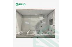
dehumidification device. 4. There is an observation window on the door. The test box has
double doors and is sealed with double layers of aging-resistant
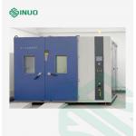
silicone rubber. 5. The outer wall material of the test room and whirlpool duct is
made of high-strength double-sided galvanized steel plate with fine
powder baking paint on the surface. The inner wall is processed and
formed by SUS304 stainless steel plate. The frame is made of 10#
square tube after anti-rust treatment and spraying. 6. Temperature and humidity control uses an intelligent controller
(relative humidity uses a direct-reading sensor) (panel control
uses a touch screen). Dust blowing method from top to bottom (vertical), the dust blowing
time can be controlled by program. Cabinet Configuration
a) Shell: Made of 1.0mm high-quality color steel plate, the outer
surface is painted, and the color is white. b) Insulation layer: 100mm polyurethane foam. C) Inner chamber: Made of 1.2mm thick SUS 304 stainless steel
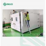
plate. Loading Platform
Loading platform load ≥500kg (unloaded), there are guide rails
inside and outside the chamber, so that the sample car can be
pushed directly into the inner chamber from the outside. Chamber door: --1 set of manual double doors, with a large
observation window and a dust wiper on the door.
--Install one observation window for each door
(2 pieces in total).
--The observation window uses multi-layer
explosion-proof glass.
--Install double-layer high and low temperature
resistant sealing silicone strips on the door. Details Introduction
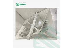
| Dust test device | a) A funnel (4 pieces in total) is installed at each of the four
corners of the studio, 2 funnels in the middle (6 funnels in
total), and a metal dust filter is installed on the upper surface
of the funnel. b) A set of rotating devices is designed between the lower part of
the loading platform and the bottom plate of the warehouse, and the
dust is swept into the funnels at the four corners through dust
brushes. c) A high-power mixed-flow fan is installed at the bottom of the
funnel to send the dust to the working room through the circulating
air duct for settlement. d) Meet the dust blowing test requirements of IP5X and IP6X. The
dust blowing airflow in the test room can make the dust evenly
suspended and distributed in the test chamber. The blowing dust
concentration is 2~4kg/m3 (adjustable). The test dust settles
evenly and slowly on the substrate. On the test sample, it does not
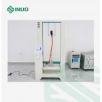
exceed 2m/s (adjustable). | | Test hole | a) The equipment is equipped with φ50 mm test holes (one on the
left and right of the machine with a diameter of 50mm) b) The test hole is equipped with sealant plug and stainless steel
hole cover. | | Lighting | a) Install LED lighting fixtures on the top of the studio for
observation. b) The lighting switch button is designed on the control panel of
the control cabinet. c) The normal use time of the lighting lamp is ≥1000H. | | Vacuum system | a) Vacuum pump: single-stage rotary vane vacuum pump (2HP) b) Sensor: Equipped with an electronic differential pressure
sensor, which can control the differential pressure of the test
piece through a pressure regulating valve to meet the corresponding
test requirements. c) The vacuum system consists of a vacuum pump, vacuum pipeline,
vacuum U-shaped pressure indicator, air flow meter, etc. Equipped
with pressure gauge, air filter, pressure regulating triple piece
and connecting pipe. d) Vacuum pipeline: The pipeline system consists of copper pipes,
rubber hoses, and air filter pressure regulating valves. e) U-shaped pressure indicator gauge: differential pressure
display. f) Air flow meter: Glass rotor flow meter measures evacuation rate
(at least 5 vacuum pressure channels) | | Dust drying system | a) A heating system is designed inside the studio for
dehumidification during testing. b) The heater uses finned stainless steel heating tubes, which are
fixed on the left and right sides of the box, and the surface is
protected by perforated stainless steel plates. c) The heater is driven by a solid-state relay and automatically
adjusted through PID to control the temperature in the working
room. d) The drying process will not affect the test process. | | Control cabinet | a) Configure an independent control cabinet for installing
electrical components. b) The control cabinet is placed in a convenient place for
operation according to user needs. | | Sample entry and exit methods | Manually or by forklift | | Others | The shell to be tested is placed in the test chamber, and a vacuum
pump is used to keep the pressure inside the shell below
atmospheric pressure. The air pressure in the test chamber can also
be changed to achieve periodic changes in the air pressure in the
test chamber. |
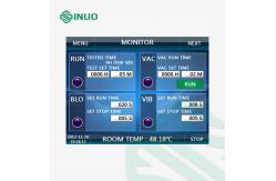
Control System
| Controller | Programmable LCD touch screen controller that can record laboratory
temperature and relative humidity | | Program execution | With four output points, four different time program executions can
be completed at the same time | | Time control | Each output point of the programmable controller has two time
period controls (i.e. start time and stop time) | | Time control method | The dust blower, dust vibration and total test time can be
controlled individually or collectively. | | Test time | The maximum is 9999 minutes | | Communication interface | RS-232C(Optional),RS-485(Optional) | | Temperature measurement | High-precision Class A PT100 platinum resistance sensor | | Conditions of use and protective devices | | Conditions of use | a) Environmental requirements: ambient temperature: -5℃~40℃;
relative humidity: ≤90%RH; atmospheric pressure: 86kPa~106kPa b) Power requirements: Voltage: 380V AC (±10%), three-phase wire +
protective ground wire, ground resistance ≤ 4Ω Frequency: 50Hz±10% c) Operating power: about 26KW, subject to final design | | Protection devices | a) Air switch: overcurrent, overheating and short circuit. b) Heating system: leakage, short circuit and overload protection,
etc. c) Studio: Adjustable over-temperature protection --- over-temperature
protection mode 1 The controller sets over-temperature shutdown alarm ---
over-temperature protection mode 2 d) Total power supply phase sequence and phase loss protection e) Leakage protection f) Equipped with three-color lights with sound and light alarm
function and door locking function g) When the protection function is implemented, the operation panel
will display the alarm number on the LCD display to inform the user
what kind of fault has occurred and cut off the main circuit power
supply. The equipment can only be started after the fault is
eliminated. h) There is an interlock device in the electrical control system.
When the circulation fan does not start or is overloaded, the
refrigeration unit and heating system cannot start. The
refrigeration unit will be disabled when the unit is under
ultra-high pressure, ultra-low pressure, or overload, and the
humidifier cannot be started when there is water shortage. i) Auxiliary functions: time signal function, input disconnection
detection function, power outage protection function, upper and
lower limit temperature and humidity alarm function, refrigeration
system automatic operation function, self-diagnosis function, water
cutoff detection function, alarm display function, timing function
(automatic start, automatic stop), backup operation function, help
function | | Equipment requirements | Includes third-party calibration (optional) |
Control Interface
Main Accessories List
| No. | Name | Brand | Quality | | 1 | Touch screen | MCGS | 1 PC | | 2 | PLC | XINJE | 1 SET | | 3 | AC contactor | Schneider | 1 SET | | 4 | Intermediate relay | Omron | 1 PC | | 5 | light button | HONGBO | 1 SET | | 6 | Alarm buzzer | HONGBO | 1 PC | | 7 | Emergency stop switch | HONGBO | 1 PC | | 8 | China Red Wave (self-locking) | HONGBO | 1 PC | | 9 | Overcurrent protector | Schneider | 1 PC | | 10 | Main power switch (circuit switch) | Schneider | 1 PC | | 11 | Switching power suppl | MEANWELL | 1 PC | | 12 | Three-phase asynchronous motor | Jiuzhou | 1 PC | | 13 | Vibration motor | Chuangxin | 1 SET | | 14 | Vortex air pump | VALUE | 1 PC | | 15 | Air flow meter | LZT Juyi | 1 PC |
|