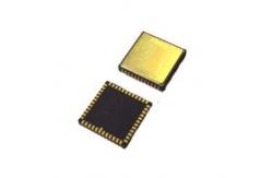
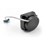
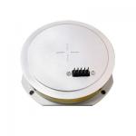
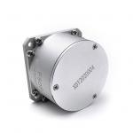
MEMS Gyro Chips High Performance Gyro PCB
PCB design:
The decoupling capacitors for pins VCP, VREF, VBUF, and VREG should
be placed as close to the pins as possible, and the equivalent
resistance of the traces should be minimized. The other ends of
the decoupling capacitors for VREF, VBUF, and VREG are connected to
the nearest AVSS _ LN and then to signal ground via a magnetic
bead. The decoupling capacitors for VCC and VIO are also placed
close to the corresponding pins. When VCC is in normal operation,
the overall current will be about 35 mA, which requires a wide PCB
trace to ensure voltage stability. For smooth assembly of the
device, try to avoid routing under the package. Locate components
to avoid areas of stress concentration. It is necessary to avoid
large heat dissipation elements and areas with external mechanical
contact, extrusion and pulling, as well as areas where positioning
screws are prone to warping during overall installation.
About product
| performance | | MGZ1 | MGZ2 | MGZ3 | MGZ4 | MGZ5 | MGZ6 |
| Range | deg/s | 500 | 500 | 500 | 400 | 400 | 8000 |
| Band Width @3DB customized) | Hz | 250 | 250 | 250 | 200 | 100 | 200 |
| Output accuracy(digital SPI) | bits | 24 | 24 | 24 | 24 | 24 | 24 |
| Output rate(ODR)(customized) | Hz | 12K | 12K | 12K | 12K | 12K | 12K |
| Delay(customized) | ms | <2 | <2 | <2 | <2 | <3 | <2 |
| Bias stability(Allan Curve@25℃) | deg/hr(1o) | <0.5 | <0.2 | <0.3 | <0.1 | <0.1 | <5 |
| Bias stability(10saverage@25℃) | deg/hr(1o) | <3 | <1 | <2.5 | <0.5 | <0.5 | <20 |
| Bias stability(1serror@25℃) | deg/hr(1o) | <9 | <3 | <7.5 | <1.5 | <1.5 | <60 |
| Bias temperature drift | deg/Hr/C | <2 | <1 | <2 | <0.5 | <0.5 | <5 |
| Bias repeatability(25℃) | deg/hr(1o) | <3 | <1 | <3 | <0.5 | <0.5 | <5 |
| Scare factor repeatability(25℃) | ppm(1o) | <50ppm | <50ppm | <50ppm | <50ppm | <20ppm | <10ppm |
| Scare factor drift(1sigma) | ppm(1o) | ±200ppm | ±200ppm | ±200ppm | ±200ppm | ±100ppm | ±100ppm |
| Scare factor nonlinear(in full temperature) | ppm | <300ppm | <300ppm | <300ppm | <300ppm | <200ppm | <100ppm |
| Angular random walk(ARW) | °/√h | <0.15 | <0.15 | <0.125 | <0.025 | <0.025 | <1 |
| Resolution | °/hr | <1 | <0.5 | <1 | <0.1 | <0.1 | <5 |
| Noise(Peak to Peak) | deg/s | <±0.25 | <±0.20 | <±0.2 | <±0.1 | <±0.1 | <±1 |
| GValue sensitivity | °/hr/g | <3 | <1 | <3 | <1 | <1 | <3 |
| Vibration rectification error(12gRMS,20-2000) | °/hr/g(rms) | <3 | <1 | <3 | <1 | <1 | <1 |
| Power-on time (valid data) | s | 1 | 1 | 1 | 1 | 1 | 1 |
| Environmental suitability | | | | | | | |
| Impact (power on) | 500g (1ms, 1/2 sine) |
| Impact resistance (power off) | 1wg 5ms |
| vibration(power on) | 12g rms (20Hz to 2kHz) |
| Working temperature | -45℃----+85℃ |
| Store temperature | -50℃----+105℃ |
| High overload resistance(poweroff) | | 10000g | 20000g |
Installation
High-performance MEMS gyroscope is a high-precision test equipment.
In order to achieve the best effect of design, it is recommended to
consider the following aspects when installing the device on the
PCB board: 1. In order to evaluate and optimize the placement of
the sensor on the PCB, it is recommended to consider the following
aspects and use additional tools during the design phase: On the
thermal side; For mechanical stress: bending measurement and/or
finite element simulation; Robustness to impact: After the PCB of
the target application has been soldered in the recommended manner,
a drop test is performed. 2. It is recommended to maintain a
reasonable distance between the mounting position of the sensor on
the PCB and the key points described below (the exact value of
"reasonable distance" depends on many customer-specific variables
and must therefore be determined on a case-by-case basis): It is
generally recommended to keep the PCB thickness to a minimum
(recommended: 1.6 ~ 2.0 mm), because the inherent stress of a thin
PCB board is small; It is not recommended to place the sensor
directly under the button or close to the button because of
mechanical stress; It is not recommended to place the sensor near
a very hot spot, such as a controller or graphics chip, as this can
heat the PCB board and cause the temperature of the sensor to rise.