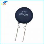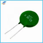
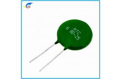
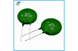
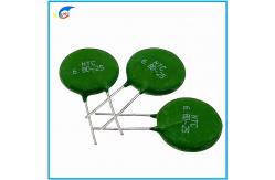
Practical MF72 6.8D-25 6R8 Ohm Ntc Thermistor Sensor
|
|
Practical MF72 Power NTC Thermistor 6.8D-25 6.8Ohm 25mm Suitable For Switching Power Supply Inverter Power Supply
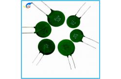
MF72 Power NTC Thermistor Series Small size, high power, strong ability to suppress surge current ●Introduction When you turn on an electrical equipment, the surge current can be restrained by a power NTC termistor connected in series with the power circuit. Because of the continuing action of current,temperature of power NTC thermistor raising, the resistance will rapidly drop to a small value, the consumed power can be ignored. So it can't affect normal operating current. Therefore, using power NTC thermistor is a most effectively and most brief measure to restrain surge current, protecting electrical equipment from destruction. ●Applications ◎Conversion power-supply, switch power-supply, ups power-supply ◎Electronic energy saving lamps, electronic ballast and all kinds of electric heater ◎All kinds of RT, display ◎ Bulb and other lighting lamps
●Characteristics ◎Small size, strong power and strong capability of surge current protection. ◎ Fast response to surge current ◎ Big material constant (B value), Small remain resistance ◎Longevity of service. High reliability ◎ Integral series, extensive operating range
● MAIN TECHNICAL PARAMETER
●Dimensions(mm)
MF72 power type NTC thermistor series Negative temperature coefficient thermistor, also known as NTC thermistor, is a kind of sensor resistance whose resistance value decreases with the increase of temperature. Widely used in various electronic components, such as temperature sensors, resettable fuses and self-adjusting heaters, etc. Features
Application
|
|||||||||||||||||||||||||||||||||||||||||||||||||||||||||||||||||||||||||||||||||||||||||||||||||||||||||||||||||||||||||||||||||||||||||||||||||||||||||||||||||||||||||||||||||||||||||||||||||||||||||||||||||||||||||||||||||||||||||||||||||||||||||||||||||||||||||||||||||||||||||||||||||||||||||||||||||||||||||||||||||||||||||||||||||||||||||||||||||||||||||||||||||||||||||||||||||||||||||||||||||||||||||||||||||||||||||||||||||||||||||||||||||||||||||||||||||||||||||||||||||||||||||||||||||||||||||||||||||||||||||||||||||||||||||||||||||||||||||||||||||||||||||||||||||||||||||||||||||||||||||||||||||||||||||||||||||||||||||||||||||||||||||||||||||||||||||||||||||||||||||||||||||||||||||||||||||||||||||||||||||||||||||||||||||||||||||||||||||||||||||||||||||||||||||||||||||||||||||||||||||||||||||||||||||||||||||||||||||||||||||||||||||||||||||||||||||||||||||||||||||||||||||||||||||||||||||||||||||||||||||||||||||||||||||||||||||||||||||||||||||||||||||||||||||||||||||||||||||||||||


| DMAX
| Dmax | Tmax | d | F1 | F2 | Straight Leads | Bend Leads | |
| ±0.05 | ±1 | ±1.5 | Lmin | Lmin | L2±2 | |||
| MF72□D5 | 7 | 5 | 0.6 / 0.45 | 5 / 2.5 | 3 | 25 | 17/5.0 | 8/5.0 |
| MF72□D7 | 9 | 5 | 0.6 | 5 | 3 | 25 | 17/5.0 | 8/5.0 |
| MF72□D9 | 11 | 5.5 | 0.8 / 0.6 | 7.5 / 5 | 5/3 | 25 | 17/5.0 | 8/5.0 |
| MF72□D11 | 13 | 5.5 | 0.8 | 7.5 / 5 | 5/3 | 25 | 17/5.0 | 8/5.0 |
| MF72□D13 | 15.5 | 6 | 0.8 | 7.5 | 5 | 25 | 17/5.0 | 8/5.0 |
| MF72□D15 | 17.5 | 6 | 0.8 | 10 / 7.5 | 5 | 25 | 17/5.0 | 8/5.0 |
| MF72□D20 | 22.5 | 7 | 1 | 10 / 7.5 | / | 25 | / | / |
| MF72□D25 | 27.5 | 8 | 1 | 10 / 7.5 | / | 25 | / | / |
Main technical parameters:
| D-5 NTC Thermistor | |||||||
| Part Number MF72 NTC | R25 (Ω) | Max steady-state current(A) | Approximate resistance value at maximum current Ω) | Dissipation coefficient approx. (MW /℃) | Thermal time constant approx. (S) | Operating temperature (°C) | UL |
| 3D-5 | 3 | 1.3 | 0.177 | 7 | 16 | -40〜+ 150 | |
| 5D-5 | 5 | 1 | 0.353 | 7 | 16 | -40〜+ 150 | √ |
| 10D-5 | 10 | 0.7 | 0.771 | 7 | 16 | -40〜+ 150 | √ |
| 20D-5 | 20 | 0.5 | 1.154 | 6 | 17 | -40〜+ 150 | |
| 60D-5 | 60 | 0.3 | 1.878 | 6 | 17 | -40〜+ 150 | |
| 200D-5 | 200 | 0.1 | 18.7 | 5 | 17 | -40〜+ 150 | √ |
|
D-7 NTC Thermistor | |||||||
| Part Number MF72 NTC | R25 (Ω) | Max steady-state current(A) | Approximate resistance value at maximum current Ω) | Dissipation coefficient approx. (MW /℃) | Thermal time constant approx. (S) | Operating temperature (°C) | UL |
| 2.5D-7 | 2.5 | 3 | 0.132 | 11 | 27 | -40〜+ 150 | |
| 3D-7 | 3 | 2.5 | 0.145 | 11 | 27 | -40〜+ 150 | |
| 5D-7 | 5 | 2 | 0.283 | 9 | 23 | -40〜+ 150 | √ |
| 8D-7 | 8 | 1 | 0.539 | 9 | 28 | -40〜+ 150 | √ |
| 10D-7 | 10 | 1 | 0.616 | 9 | 23 | -40〜+ 150 | √ |
| 12D-7 | 12 | 1 | 0.816 | 9 | 23 | -40〜+ 150 | |
| 16D-7 | 16 | 0.7 | 1.003 | 8 | 23 | -40〜+ 150 | √ |
| 22D-7 | 22 | 0.6 | 1.108 | 8 | 23 | -40〜+ 150 | √ |
| 33D-7 | 33 | 0.5 | 1.485 | 8 | 23 | -40〜+ 150 | √ |
| 200D-7 | 200 | 0.2 | 11.65 | 7 | 21 | -40〜+ 150 | √ |
|
D-9 NTC Thermistor | |||||||
| Part Number MF72 NTC | R25 (Ω) | Max steady-state current(A) | Approximate resistance value at maximum current Ω) | Dissipation coefficient approx. (MW /℃) | Thermal time constant approx. (S) | Operating temperature (°C) | UL |
| 1.5D-9 | 1.5 | 5 | 0.3 | 11 | 36 | -40〜+ 170 | |
| 2.5D-9 | 2.5 | 4.5 | 0.06 | 11 | 36 | -40〜+ 170 | |
| 3D-9 | 3 | 4 | 0.12 | 11 | 35 | -40〜+ 170 | √ |
| 4D-9 | 4 | 3 | 0.19 | 11 | 35 | -40〜+ 170 | √ |
| 5D-9 | 5 | 3 | 0.21 | 11 | 34 | -40〜+ 170 | √ |
| 6D-9 | 6 | 2 | 0.315 | 11 | 34 | -40〜+ 170 | √ |
| 8D-9 | 8 | 2 | 0.4 | 11 | 32 | -40〜+ 170 | √ |
| 10D-9 | 10 | 2 | 0.458 | 11 | 32 | -40〜+ 170 | √ |
| 12D-9 | 12 | 1 | 0.652 | 11 | 32 | -40〜+ 170 | √ |
| 16D-9 | 16 | 1 | 0.802 | 11 | 31 | -40〜+ 170 | √ |
| 20D-9 | 20 | 1 | 0.864 | 11 | 30 | -40〜+ 170 | √ |
| 22D-9 | 22 | 1 | 0.95 | 11 | 30 | -40〜+ 170 | √ |
| 30D-9 | 30 | 1 | 1.022 | 11 | 30 | -40〜+ 170 | √ |
| 33D-9 | 33 | 1 | 1.124 | 11 | 30 | -40〜+ 170 | √ |
| 50D-9 | 50 | 1 | 1.252 | 11 | 30 | -40〜+ 170 | √ |
| 100D-9 | 100 | 0.7 | 1.356 | 11 | 28 | -40〜+ 170 | |
| 200D-9 | 200 | 0.5 | 1.485 | 10 | 28 | -40〜+ 170 | |
| 400D-9 | 400 | 0.2 | 1.652 | 9 | 25 | -40〜+ 170 | |
| D-11 NTC Thermistor | |||||||
| Part Number MF72 NTC | R25 (Ω) | Max steady-state current(A) | Approximate resistance value at maximum current Ω) | Dissipation coefficient approx. (MW /℃) | Thermal time constant approx. (S) | Operating temperature (°C) | UL |
| 1D-11 | 1 | 5.5 | 0.07 | 13 | 46 | -40〜+ 170 | |
| 1.5D-11 | 1.5 | 5.5 | 0.085 | 13 | 46 | -40〜+ 170 | |
| 2.5D-11 | 2.5 | 5 | 0.095 | 13 | 43 | -40〜+ 170 | √ |
| 3D-11 | 3 | 5 | 0.1 | 13 | 43 | -40〜+ 170 | √ |
| 4D-11 | 4 | 4 | 0.15 | 13 | 44 | -40〜+ 170 | √ |
| 5D-11 | 5 | 4 | 0.156 | 13 | 45 | -40〜+ 170 | √ |
| 6D-11 | 6 | 3 | 0.24 | 13 | 45 | -40〜+ 170 | √ |
| 8D-11 | 8 | 3 | 0.255 | 14 | 47 | -40〜+ 170 | √ |
| 10D-11 | 10 | 3 | 0.275 | 14 | 47 | -40〜+ 170 | √ |
| 12D-11 | 12 | 2 | 0.462 | 14 | 48 | -40〜+ 170 | √ |
| 16D-11 | 16 | 2 | 0.47 | 14 | 50 | -40〜+ 170 | √ |
| 20D-11 | 20 | 2 | 0.512 | 15 | 52 | -40〜+ 170 | √ |
| 22D-11 | 22 | 2 | 0.563 | 15 | 52 | -40〜+ 170 | √ |
| 30D-11 | 30 | 1.5 | 0.667 | 15 | 52 | -40〜+ 170 | √ |
| 33D-11 | 33 | 1.5 | 0.734 | 15 | 52 | -40〜+ 170 | √ |
| 50D-11 | 50 | 1.5 | 1.021 | 15 | 52 | -40〜+ 170 | √ |
| 60D-11 | 60 | 1.5 | 1.215 | 15 | 52 | -40〜+ 170 | √ |
| 80D-11 | 80 | 1.2 | 1.656 | 15 | 52 | -40〜+ 170 | √ |
| D-13 NTC Thermistor | |||||||
| Part Number MF72 NTC | R25 (Ω) | Max steady-state current(A) | Approximate resistance value at maximum current Ω) | Dissipation coefficient approx. (MW /℃) | Thermal time constant approx. (S) | Operating temperature (°C) | UL |
| 1.3D-13 | 1.3 | 7 | 0.062 | 13 | 60 | -40〜+ 200 | √ |
| 1.5D-13 | 1.5 | 7 | 0.073 | 13 | 60 | 40〜+ 200 | √ |
| 2.5D-13 | 2.5 | 6 | 0.088 | 13 | 60 | 40〜+ 200 | √ |
| 3D-13 | 3 | 6 | 0.092 | 14 | 60 | 40〜+ 200 | √ |
| 4D-13 | 4 | 5 | 0.12 | 15 | 67 | 40〜+ 200 | √ |
| 5D-13 | 5 | 5 | 0.125 | 15 | 68 | 40〜+ 200 | √ |
| 6D-13 | 6 | 4 | 0.17 | 15 | 65 | 40〜+ 200 | √ |
| 7D-13 | 7 | 4 | 0.188 | 15 | 65 | 40〜+ 200 | √ |
| 8D-13 | 8 | 4 | 0.194 | 15 | 60 | 40〜+ 200 | √ |
| 10D-13 | 10 | 4 | 0.206 | 15 | 65 | 40〜+ 200 | √ |
| 12D-13 | 12 | 3 | 0.316 | 16 | 65 | 40〜+ 200 | √ |
| 15D-13 | 15 | 3 | 0.335 | 16 | 60 | 40〜+ 200 | √ |
| 16D-13 | 16 | 3 | 0.338 | 16 | 60 | 40〜+ 200 | √ |
| 20D-13 | 20 | 3 | 0.372 | 16 | 65 | 40〜+ 200 | √ |
| 30D-13 | 30 | 2.5 | 0.517 | 16 | 65 | 40〜+ 200 | √ |
| 47D-13 | 47 | 2 | 0.81 | 17 | 65 | 40〜+ 200 | √ |
| 120D-13 | 120 | 1.2 | 2.124 | 17 | 65 | 40〜+ 200 | √ |
|
D-15 NTC Thermistor | |||||||
| Part Number MF72 NTC | R25 (Ω) | Max steady-state current(A) | Approximate resistance value at maximum current Ω) | Dissipation coefficient approx. (MW /℃) | Thermal time constant approx. (S) | Operating temperature (°C) | UL |
| 1.3D-15 | 1.3 | 8 | 0.048 | 18 | 68 | -40〜+ 200 | √ |
| 1.5D-15 | 1.5 | 8 | 0.052 | 18 | 69 | -40〜+ 200 | √ |
| 2.5D-15 | 2.5 | 7 | 0.065 | 18 | 76 | -40〜+ 200 | √ |
| 3D-15 | 3 | 7 | 0.075 | 18 | 76 | -40〜+ 200 | √ |
| 5D-15 | 5 | 6 | 0.112 | 20 | 76 | -40〜+ 200 | √ |
| 6D-15 | 6 | 5 | 0.155 | 20 | 80 | -40〜+ 200 | √ |
| 7D-15 | 7 | 5 | 0.173 | 20 | 80 | -40〜+ 200 | √ |
| 8D-15 | 8 | 5 | 0.178 | 20 | 80 | -40〜+ 200 | √ |
| 10D-15 | 10 | 5 | 0.18 | 20 | 75 | -40〜+ 200 | √ |
| 12D-15 | 12 | 4 | 0.25 | 20 | 75 | -40〜+ 200 | √ |
| 15D-15 | 15 | 4 | 0.268 | 21 | 85 | -40〜+ 200 | √ |
| 16D-15 | 16 | 1 | 0.276 | 21 | 70 | -40〜+ 200 | √ |
| 20D-15 | 20 | 4 | 0.288 | 21 | 86 | -40〜+ 200 | √ |
| 30D-15 | 30 | 3.5 | 0.438 | 21 | 75 | -40〜+ 200 | √ |
| 47D-15 | 47 | 3 | 0.68 | 21 | 86 | -40〜+ 200 | √ |
| 120D-15 | 120 | 1.8 | 1.652 | 22 | 87 | -40〜+ 200 | √ |
| 220D-15 | 220 | 1 | 2.0358 | 24 | 90 | -40〜+ 20 | |
|
D-20 NTC Thermistor | |||||||
| Part Number MF72 NTC | R25 (Ω) | Max steady-state current(A) | Approximate resistance value at maximum current Ω) | Dissipation coefficient approx. (MW /℃) | Thermal time constant approx. (S) | Operating temperature (°C) | UL |
| 0.7D-20 | 7 | 11 | 0.018 | 27 | 89 | -40〜+ 200 | √ |
| 1D-20 | 1 | 10 | 0.023 | 27 | 89 | -40〜+ 200 | |
| 1.3D-20 | 1.3 | 9 | 0.037 | 27 | 88 | -40〜+ 200 | √ |
| 3D-20 | 3 | 8 | 0.055 | 25 | 88 | -40〜+ 200 | √ |
| 5D-20 | 5 | 7 | 0.087 | 25 | 87 | -40〜+ 200 | √ |
| 6D-20 | 6 | 6 | 0.113 | 25 | 103 | -40〜+ 200 | √ |
| 8D-20 | 8 | 6 | 0.142 | 25 | 105 | -40〜+ 200 | √ |
| 10D-20 | 10 | 6 | 0.162 | 24 | 102 | -40〜+ 200 | √ |
| 12D-20 | 12 | 5 | 0.195 | 24 | 100 | -40〜+ 200 | √ |
| 16D-20 | 16 | 5 | 0.212 | 24 | 100 | -40〜+ 200 | √ |
| 20D-20 | 20 | 4.5 | 0.345 | 23 | 115 | -40〜+ 200 | |
| 30D-20 | 30 | 4 | 0.492 | 23 | 115 | -40〜+ 200 | |
| 47D-20 | 47 | 3.5 | 0.675 | 23 | 120 | -40〜+ 200 | |
|
D-25 NTC Thermistor | |||||||
| Part Number MF72 NTC | R25 (Ω) | Max steady-state current(A) | Approximate resistance value at maximum current Ω) | Dissipation coefficient approx. (MW /℃) | Thermal time constant approx. (S) | Operating temperature (°C) | UL |
| 0.7D-25 | 0.7 | 12 | 0.014 | 30 | 120 | -40〜+ 200 | |
| 1.5D-25 | 1.5 | 10 | 0.027 | 30 | 121 | -40〜+ 200 | |
| 3D-25 | 3 | 9 | 0.044 | 32 | 124 | -40〜+ 200 | |
| 5D-25 | 5 | 8 | 0.07 | 32 | 125 | -40〜+ 200 | |
| 8D-25 | 8 | 7 | 0.114 | 33 | 125 | -40〜+ 200 | |
| 10D-25 | 10 | 7 | 0.13 | 32 | 127 | -40〜+ 200 | |
| 12D-25 | 12 | 6 | 0.156 | 32 | 126 | -40〜+ 200 | |
| 16D-25 | 16 | 6 | 0.16 | 35 | 126 | -40〜+ 200 | |
| 20D-25 | 20 | 4.5 | 0.184 | 35 | 126 | -40〜+ 200 | |
Note: Multiple resistance values and pin types can be customized on demand.
What is an inrush current suppression power type NTC thermistor
A power NTC thermistor can be a cost-effective device for limiting the amount of inrush current in a switching power supply or other equipment when power is first applied. A power NTC thermistor limits inrush current by acting as a power resistor that drops from a high cold resistance to a low hot resistance when heated by the current flowing through it.
The inrush current limiter supplies the NTC thermistor protection circuit with unnecessarily high current, suppressing high inrush current surges while its resistance remains negligible during continuous operation. Due to its low resistance in the operating state, power thermistors dissipate much less power than fixed resistors commonly used in this application.
Application of Inrush Current Suppression Power Type NTC Thermistor
Limiting inrush current, suitable for protection of switching power supplies, UPS power supplies, transformers, motors, various electric heating appliances, energy-saving lamps, ballasts, various power circuits, amplifiers, color displays, monitors, color TVs, filament protection, etc.
Power thermistor elements can also be used for soft starting of motors, for example, in vacuum cleaners with a continuous current of up to 20 A.
Inrush current suppression power type NTC thermistor advantages:
· Low-cost solid-state device for suppressing inrush current.
· Minimizes line current distortion and radio noise.
· Protects switches, rectifier diodes and smoothing capacitors from premature failure.
· Prevents false fuse blowing.
Inrush current suppression power type NTC thermistor features:
· Resin coated disc thermistor with non-insulated leads.
· Suitable for AC and DC circuits up to 265 V (rms).
· Wide range of resistances, currents and sizes.
· Excellent mechanical strength.
· Suitable for PCB mounting.
Several factors to consider when selecting an inrush current suppression power NTC thermistor
1) Maximum operating current > actual operating current in the power circuit
2) At 25°CRated zero power resistance, E: loop voltage, Im: surge current
For conversion power, recovery power, switching power, UPS power, Im = 100 times the operating current For filaments, heaters, Im = 30 times the operating current
3) The larger the B value, the smaller the residual resistance and the lower the operating temperature.
4) Generally speaking, the larger the time constant and dissipation coefficient, the larger the NTC thermal capacity, and the stronger the surge current suppression capability of the NTC thermistor.
Inrush Current Suppression Power Type NTC Thermistor Application Notes
1) For inrush current limiting, the NTC thermistor must be connected in series with the load circuit. Several inrush current limiters can also be connected in series for higher damping. Inrush current limiters must not be connected in parallel.
2) Generally, inrush current limiters need time to return to a cold state, where they can provide adequate inrush current limiting due to their high resistance. The cooling time depends on the ambient conditions.
3) It should be taken into account that the surrounding area of the NTC thermistor may become hot. Make sure that adjacent components are kept at a sufficient distance from the thermistor to ensure a proper cooling time for the thermistor.
4) Make sure that the design operating temperature of the adjacent materials is comparable to the surface temperature of the thermistor. Make sure that the surrounding components and materials can withstand this temperature.
5) Ensure that the thermistor is adequately ventilated to avoid overheating.
6) Avoid contamination of the thermistor surface.
7) Avoid contact of the NTC thermistor with any liquids and solvents. M
| Because the thermistor is basically customized products, the price of goods is not the original price, the price is subject to the formal quotation. | |
| Features | RoHS compliant |
| Halogen-Free (HF) series are available | |
| Body size: Ф5mm | |
| Radial lead resin coated | |
| Operating temperature range: -30℃~+125℃ | |
| Wide resistance range | |
| Cost effective | |
| Recommended Applications | Home appliances;Automotive electronics; Computers;Switch mode power supplies;Adapters |
| | Storage Temperature: -10℃~+40℃ |
| Relative Humidity: ≦75%RH | |
| Keep away from corrosive atmosphere and sunlight. | |
| Period of Storage | 1 year |
| P/N | R@25℃ | Tolerance(%) | Beta Value | Tolerance(%) |
| MF11-050 | 5 | ±5 ±10 ±20 | 2400 | ±5 ±10 |
| MF11-100 | 10 | 2800 | ||
| MF11-150 | 15 | 2800 | ||
| MF11-200 | 20 | 2800 | ||
| MF11-220 | 22 | 2800 | ||
| MF11-270 | 27 | 3000 | ||
| MF11-330 | 33 | 3000 | ||
| MF11-390 | 39 | 3000 | ||
| MF11-470 | 47 | 3100 | ||
| MF11-500 | 50 | 3100 | ||
| MF11-680 | 68 | 3100 | ||
| MF11-820 | 82 | 3100 | ||
| MF11-101 | 100 | 3200 | ||
| MF11-121 | 120 | 3200 | ||
| MF11-151 | 150 | 3200 | ||
| MF11-201 | 200 | 3200 | ||
| MF11-221 | 220 | 3500 | ||
| MF11-271 | 270 | 3500 | ||
| MF11-331 | 330 | 3500 | ||
| MF11-391 | 390 | 3500 | ||
| MF11-471 | 470 | 3500 | ||
| MF11-501 | 500 | 3500 | ||
| MF11-561 | 560 | 3500 | ||
| MF11-681 | 680 | 3800 | ||
| MF11-821 | 820 | 3800 | ||
| MF11-102 | 1000 | 3800 | ||
| MF11-122 | 1200 | 3800 | ||
| MF11-152 | 1500 | 3800 | ||
| MF11-202 | 2000 | 4000 | ||
| MF11-222 | 2200 | 4000 | ||
| MF11-272 | 2700 | 4000 | ||
| MF11-302 | 3000 | 4000 | ||
| MF11-332 | 3300 | 4000 | ||
| MF11-392 | 3900 | 4000 | ||
| MF11-472 | 4700 | 4050 | ||
| MF11-502 | 5000 | 4050 | ||
| MF11-562 | 5600 | 4050 | ||
| MF11-682 | 6800 | 4050 | ||
| MF11-822 | 8200 | 4050 | ||
| MF11-103 | 10000 | 4050 | ||
| MF11-123 | 12000 | 4050 | ||
| MF11-153 | 15000 | 4150 | ||
| MF11-203 | 20000 | 4300 | ||
| MF11-303 | 30000 | 4300 | ||
| MF11-473 | 47000 | 4300 | ||
| MF11-503 | 50000 | 4300 | ||
| MF11-683 | 68000 | 4300 | ||
| MF11-104 | 100000 | 4500 | ||
| MF11-124 | 120000 | 4700 | ||
| MF11-154 | 150000 | 4700 | ||
| MF11-204 | 200000 | 4700 | ||
| MF11-304 | 300000 | 4700 | ||
| MF11-504 | 500000 | 4800 | ||
| MF11-105 | 1000000 | 4900 |

Negative temperature coefficient thermistor, also known as NTC thermistor, is a kind of sensor resistance whose resistance value decreases with the increase of temperature. Widely used in various electronic components, such as temperature sensors, resettable fuses and self-adjusting heaters, etc.