
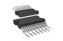
7w+7w Dual Bridge Amplifier Integrated Circuit Chip TDA7266SA
|
|
7W+7W DUAL BRIDGE AMPLIFIER
■ WIDE SUPPLY VOLTAGE RANGE (3.5-18V) ■ MINIMUM EXTERNAL COMPONENTS – NO SWR CAPACITOR – NO BOOTSTRAP – NO BOUCHEROT CELLS – INTERNALLY FIXED GAIN ■ STAND-BY & MUTE FUNCTIONS ■ SHORT CIRCUIT PROTECTION ■ THERMAL OVERLOAD PROTECTION
TECHNOLOGY BI20II
Pin to pin compatible with: TDA7266S, TDA7266, TDA7266M, TDA7266MA, TDA7266B, TDA7297SA & TDA7297.
DESCRIPTION The TDA7266SA is a dual bridge amplifier specially designed for LCD Monitor, PC Motherboard, TV and Portable Radio applications.
BLOCK AND APPLICATION DIAGRAM
ABSOLUTE MAXIMUM RATINGS
PIN CONNECTION (Top view)
APPLICATION SUGGESTION STAND-BY AND MUTE FUNCTIONS
(A) Microprocessor Application In order to avoid annoying "Pop-Noise" during Turn-On/Off transients, it is necessary to guarantee the right Stby and mute signals sequence. It is quite simple to obtain this function using a microprocessor (Fig. 1 and 2). At first St-by signal (from µP) goes high and the voltage across the St-by terminal (Pin 7) starts to increase exponentially. The external RC network is intended to turn-on slowly the biasing circuits of the amplifier, this to avoid "POP" and "CLICK" on the outputs. When this voltage reaches the St-by threshold level, the amplifier is switched-on and the external capacitors in series to the input terminals (C3, C53) start to charge. It's necessary to mantain the mute signal low until the capacitors are fully charged, this to avoid that the device goes in play mode causing a loud "Pop Noise" on the speakers. A delay of 100-200ms between St-by and mute signals is suitable for a proper operation.
Figure 1. Microprocessor Application
Figure 2. Microprocessor Driving Signals
|
||||||||||||||||||||||||
| Product Tags: electronics ic chip integrated circuit components |
|
AD8552ARUZ Electronic IC Chip NEW AND ORIGINAL STOCK |
|
BA10358F-E2 Electronic IC Chip NEW AND ORIGINAL STOCK |
|
BA14741F-E2 Electronic IC Chip NEW AND ORIGINAL STOCK |
|
DRV602PWR Flash Memory IC NEW AND ORIGINAL STOCK |
|
OPA335AIDR Electronic IC Chips SINGLE-SUPPLY CMOS OPERATIONAL AMPLIFIERS |
|
OP90GSZ-REEL7 Electronic IC Chips Low-Voltage Operational Amplifier |