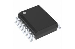
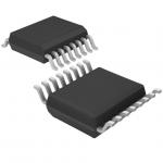
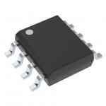
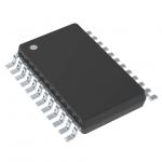
AD694ARZ Transmitter ic digital electronics / circuit board electronics
|
|
AD694ARZ Circuit Board Chips Integrated Circuit Chip 4–20 mA Transmitter
STOCK LIST
Feature
4–20 mA, 0–20 mA Output Ranges Precalibrated Input Ranges: 0 V to 2 V, 0 V to 10 V Precision Voltage Reference Programmable to 2.000 V or 10.000 V Single or Dual Supply Operation Wide Power Supply Range: 4.5 V to 36 V Wide Output Compliance Input Buffer Amplifier Open-Loop Alarm Optional External Pass Transistor to Reduce Self-Heating Errors 0.002% Typ Nonlinearity
PRODUCT HIGHLIGHTS
1. The AD694 is a complete voltage in to 4–20 mA out current transmitter. 2. Pin programmable input ranges are precalibrated at 0 V to 2 V and 0 V to 10 V. 3. The input amplifier may be configured to buffer and scale the input voltage, or to serve as an output amplifier for current output DACs. 4. The output voltage compliance extends to within 2 V of the positive supply and below common. When operated with a 5 V supply, the output voltage compliance extends 30 V below common. 5. The AD694 interfaces directly to 8-, 10-, and 12-bit single supply CMOS and bipolar DACs. 6. The 4 mA zero current may be switched on and off with a TTL control pin, allowing 0–20 mA operation. 7. An open collector alarm warns of loop failure due to open wires or noncompliance of the output stage. 8. A monitored output is provided to drive an external pass transistor. The feature off-loads power dissipation to extend the temperature range of operation and minimize self-heating error.
ABSOLUTE MAXIMUM RATINGS Supply Voltage . . . . . . . . . . . . . . . . . . . . . . . . . . . . . . . . . .36 V VS to IOUT . . . . . . . . . . . . . . . . . . . . . . . . . . . . . . . . . . . . .36 V Input Voltage, (Either Input Pin 2 or 3) . . . . . –0.3 V to +36 V Reference Short Circuit to Common . . . . . . . . . . . . Indefinite Alarm Voltage, Pin 10 . . . . . . . . . . . . . . . . . . . . . . . . . . . .36 V 4 mA Adj, Pin 6 . . . . . . . . . . . . . . . . . . . . . . . . . . . . . . . . . .1 V 4 mA On/Off, Pin 9 . . . . . . . . . . . . . . . . . . . . . . . . 0 V to 36 V Storage Temperature Range AD694Q . . . . . . . . . . . . . . . . . . . . . . . . . .–65°C to +150°C AD694N, R . . . . . . . . . . . . . . . . . . . . . . . .–65°C to +125°C Lead Temperature, 10 sec Soldering . . . . . . . . . . . . . . . 300°C Maximum Junction Temperature . . . . . . . . . . . . . . . . . 150°C Maximum Case Temperature Plastic Package (N, R) . . . . . . . . . . . . . . . . . . . . . . . . 125°C Cerdip Package (Q) . . . . . . . . . . . . . . . . . . . . . . . . . . 125°C ORDERING GUIDE Temperature Package Model Range Option * AD694JN 0°C to 70°C N-16 AD694AQ –40°C to +85°C Q-16 AD694AR –40°C to +85°C R-16 AD694BQ –40°C to +85°C Q-16 AD694BR –40°C to +85°C R-16 *N = Plastic DIP; Q = CERDIP, R = SOIC Transistor Count: . . . . . . . . . . . . . . . . . . . . .75 Active Devices Substrate Connection: . . . . . . . . . . . . . . . . . . . . to Com, Pin 5 Thermal Characteristics: Plastic (N) Package: θJC = 50°C/Watt θCA (Still Air) = 85°C/Watt Cerdip (Q) Package: θJC = 30°C/Watt θCA (Still Air) = 70°C/Watt Plastic (R) Package: θJC = 27°C/Watt θCA (Still Air) = 73°C/Watt |
||||||||||||||||||||||||||||||||||||||||||||||||||||||||||||||||||||||||||||||||||||||||||||||||||||||||||||||||||||||||
| Product Tags: electronic chip board electronic components ic |

