
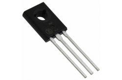
Plastic DarliCM GROUPon complementary power mosfet , Silicon Power Transistors 2N6038
|
|
Plastic DarliCM GROUPon complementary power mosfet , Silicon Power Transistors 2N6038
Plastic DarliCM GROUPon complementary silicon power transistors are designed for general purpose amplifier and low−speed switching applications.
• High DC Current Gain — hFE = 2000 (Typ) @ IC = 2.0 Adc • Collector–Emitter Sustaining Voltage — @ 100 mAdc VCEO(sus) = 60 Vdc (Min) — 2N6035, 2N6038 = 80 Vdc (Min) — 2N6036, 2N6039 • Forward Biased Second Breakdown Current Capability IS/b = 1.5 Adc @ 25 Vdc • Monolithic Construction with Built–In Base–Emitter Resistors to LimitELeakage Multiplication • Space–Saving High Performance–to–Cost Ratio TO–225AA Plastic Package
Stresses exceeding Maximum Ratings may damage the device. Maximum Ratings are stress ratings only. Functional operation above the Recommended Operating Conditions is not implied. Extended exposure to stresses above the Recommended Operating Conditions may affect device reliability.
*Indicates JEDEC Registered Data.
|
|||||||||||||||||||||||||||||||||||||||||||||||||||||||||||||||||||||||||||||||||||||||||||||||||||||||||||||||||||||||||||
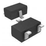
| Product Tags: npn smd transistor multi emitter transistor |
|
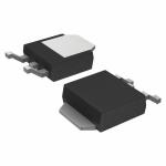
RB450FT106 Rectifier Diode Schottky barrier diode diode laser hair removal |
|
TK10P60W Power Mosfet Transistor MOSFETs Silicon N-Channel MOS |
|
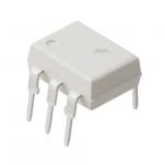
4N25M Electronic IC Chips General Purpose Phototransistor Optocouplers |
|
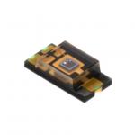
TEMT6000X01 Electronic IC Chips Ambient Light Sensor, RoHS Compliant |
|
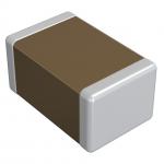
GRM033R71C272KA88D NEW AND ORIGINAL STOCK |
|
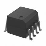
FOD2742B Flash Memory IC NEW AND ORIGINAL STOCK |