
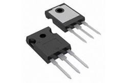
IRFP150N Transistor Electronics Components electronic devices N-Channel Power MOSFET
|
|
IRFP150N Transistor Electronics Components electronic devices N-Channel Power MOSFET
Features • Ultra Low On-Resistance - rDS(ON) = 0.030Ω, VGS = 10V • Simulation Models - Temperature Compensated PSPICE™ and SABER© Electrical Models - Spice and SABER© Thermal Impedance Models - www.fairchildsemi.com • Peak Current vs Pulse Width Curve • UIS Rating Curve
Absolute Maximum Ratings TC = 25oC, Unless Otherwise Specified Drain to Source Voltage (Note 1) . . . . . . . . . . . . . . . . . . . . . . . . . . VDSS 100 V Drain to Gate Voltage (RGS = 20kΩ) (Note 1) . . . . . . . . . . . . . . . . . . VDGR 100 V Gate to Source Voltage . . . . . . . . . . . . . . . . . . . . .. . . . . . . . . . . VGS ±20 V Drain Current Continuous (TC= 25oC, VGS = 10V) (Figure 2) . . .. . . . . . . . . . . . . ID Continuous (TC= 100oC, VGS = 10V) (Figure 2) . . . . . . . . . . . . ID Pulsed Drain Current . . . . . . . . . . . . . . . . . . . . . . . . . . .IDM 44 31 Figure 4 A A Pulsed Avalanche Rating . . . . . . . . . . . . . . . . . . . . . .UIS Figures 6, 14, 15 Power Dissipation . . . . . . . . . . . . . . . . . . . . . PD Derate Above 25oC . . . . . . . . . . . . . . . . . . . . . . . . 155 1.03 W W/oC Operating and Storage Temperature . . . . . . . . . TJ, TSTG -55 to 175 oC Maximum Temperature for Soldering Leads at 0.063in (1.6mm) from Case for 10s. ... . .TL Package Body for 10s, See Techbrief TB334 . . . . . . . . . Tpkg 300 260 oC oC |
||||||||||||||||||||||||||||||||||||||||||||||||||||||||||||||||||||||||||||||||||||||||||||||||||||||||||||||||||||||||
| Product Tags: npn smd transistor multi emitter transistor |
|
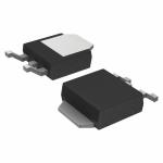
RB450FT106 Rectifier Diode Schottky barrier diode diode laser hair removal |
|
TK10P60W Power Mosfet Transistor MOSFETs Silicon N-Channel MOS |
|
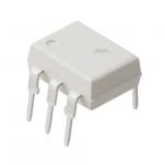
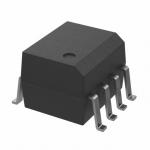
4N25M Electronic IC Chips General Purpose Phototransistor Optocouplers |
|
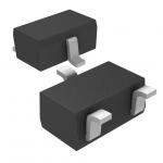
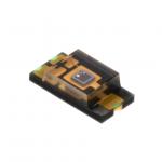
TEMT6000X01 Electronic IC Chips Ambient Light Sensor, RoHS Compliant |
|
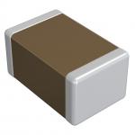
GRM033R71C272KA88D NEW AND ORIGINAL STOCK |
|
FOD2742B Flash Memory IC NEW AND ORIGINAL STOCK |