
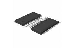
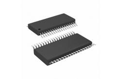
MSP430F2252IDAR Integrated Circuit Chip new & original MIXED SIGNAL MICROCONTROLLER
|
|
MSP430x22x2, MSP430x22x4 MIXED SIGNAL MICROCONTROLLER
description The Texas Instruments MSP430 family of ultralow-power microcontrollers consist of several devices featuring different sets of peripherals targeted for various applications. The architecture, combined with five low-power modes is optimized to achieve extended battery life in portable measurement applications. The device features a powerful 16-bit RISC CPU, 16-bit registers, and constant generators that contribute to maximum code efficiency. The digitally controlled oscillator (DCO) allows wake-up from low-power modes to active mode in less than 1 μs. The MSP430x22xx series is an ultralow-power mixed signal microcontroller with two built-in 16-bit timers, a universal serial communication interface, 10-bit A/D converter with integrated reference and data transfer controller (DTC), two general-purpose operational amplifiers in the MSP430x22x4 devices, and 32 I/O pins. Typical applications include sensor systems that capture analog signals, convert them to digital values, and then process the data for display or for transmission to a host system. Stand-alone radio-frequency (RF) sensor front ends are another area of application.
absolute maximum ratings (see Note 1) Voltage applied at VCC to VSS . . . . . . . . . . . . . . . . . . . . . . . . . . . . . . . . . . . . . . . . −0.3 V to 4.1 V Voltage applied to any pin (see Note 2) . . . . . . . . . . . . . . . . . . . . . . . . . . . . −0.3 V to VCC+0.3 V Diode current at any device terminal . . . . . . . . . . . . . . . . . . . . . . . . . . . . . . . . . . . . . . . . . . ±2 mA Storage temperature range, Tstg (unprogrammed device, see Note 3) . . . . . . . . .−55 °C to 150°C Storage temperature range, Tstg (programmed device, see Note 3) . . . . . . . . . . . −40°C to 105°C
NOTES: 1. Stresses beyond those listed under “absolute maximum ratings” may cause permanent damage to the device. These are stress ratings only, and functional operation of the device at these or any other conditions beyond those indicated under “recommended operating conditions” is not implied. Exposure to absolute-maximum-rated conditions for extended periods may affect device reliability. 2. All voltages referenced to VSS. The JTAG fuse-blow voltage, VFB, is allowed to exceed the absolute maximum rating. The voltage is applied to the TEST pin when blowing the JTAG fuse. 3. Higher temperature may be applied during board soldering process according to the current JEDEC J-STD-020 specification with peak reflow temperatures not higher than classified on the device label on the shipping boxes or reels.
Stock Offer (Hot Sell)
|
||||||||||||||||||||||||||||||||||||||||||||||||||||||||||||||||||||||||||||||||||||||||||||||||||||||||||||||
| Product Tags: electronic integrated circuit linear integrated circuits |
|
AT89C2051-24PU Electronic IC Chip NEW AND ORIGINAL STOCK |
|
MC9S08GT32ACFBE Flash Memory IC NEW AND ORIGINAL STOCK |
|
MC9S08AC60CFGE Flash Memory IC NEW AND ORIGINAL STOCK |

|
MC9S08AW32CFGE Flash Memory IC NEW AND ORIGINAL STOCK |
|
MC9S08AW32CPUE Flash Memory IC NEW AND ORIGINAL STOCK |
|
MC68332GCAG16 Flash Memory IC NEW AND ORIGINAL STOCK |