
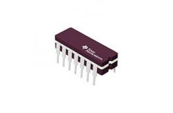
SN74HC04N Electronic IC Chips Integrated Components HEX INVERTERS
|
|
Stock Offer (Hot Sell)
SN54HC04, SN74HC04 HEX INVERTERS
description The ’HC04 devices contain six independent inverters. They perform the Boolean function Y = A in positive logic.
absolute maximum ratings over operating free-air temperature range (unless otherwise noted)†
Supply voltage range, VCC . . . . . . . . . . . . . . . . . . . . . . . . . . . . . . . . . . . . . . . . . . . . . . . –0.5 V to 7 V Input clamp current, IIK (VI < 0 or VI > VCC) (see Note 1) . . . . . . . . . . . . . . . . . . . . . . . . . . . . . ±20 mA Output clamp current, IOK (VO < 0 or VO > VCC) (see Note 1) . . . . . . . . . . . . . . . . . . . . . . . . . ±20 mA Continuous output current, IO (VO = 0 to VCC) . . . . . . . . . . . .. . . . . . . . . . . . . . . . . . . . . . . . . . ±25 mA Continuous current through VCC or GND . . . . . . . . . . . . . .. . . . . . . . . . . . . . . . . . . . . . . . . . . . ±50 mA Package thermal impedance, θJA (see Note 2): D package . . . . . . . . . . . . . . . . . . . . . . . . . . 86 °C/W N package . . . . . . . . . . . . . . . . . . . . . . . . . . 80 °C/W NS package . . . . . . . . . . . . . . . . . . . . . . . . . . 76 °C/W PW package . . . . . . . . . . . . . . . . . . . . . . . . 113 °C/W Storage temperature range, Tstg . . . . . . . . . . . . . . . . . . . . . . . . . . . . . . . . . . . . . . . . . –65°C to 150°C
†Stresses beyond those listed under “absolute maximum ratings” may cause permanent damage to the device. These are stress ratings only, and functional operation of the device at these or any other conditions beyond those indicated under “recommended operating conditions” is not implied. Exposure to absolute-maximum-rated conditions for extended periods may affect device reliability. NOTES: 1. The input and output voltage ratings may be exceeded if the input and output current ratings are observed. 2. The package thermal impedance is calculated in accordance with JESD 51-7.
|
|||||||||||||||||||||||||||||||||||||||||||||||||||||||||||||||||||||||||||||||||||||||||||||||||||||||||||||||||||||||||||||||||||||||||||||||||||||||||||
| Product Tags: electronic integrated circuit linear integrated circuits |
|
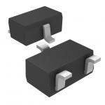
RB450FT106 Rectifier Diode Schottky barrier diode diode laser hair removal |
|
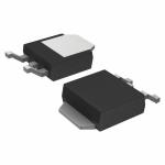
TK10P60W Power Mosfet Transistor MOSFETs Silicon N-Channel MOS |
|
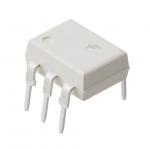
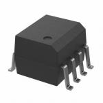
4N25M Electronic IC Chips General Purpose Phototransistor Optocouplers |
|
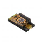
TEMT6000X01 Electronic IC Chips Ambient Light Sensor, RoHS Compliant |
|
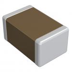
GRM033R71C272KA88D NEW AND ORIGINAL STOCK |
|
FOD2742B Flash Memory IC NEW AND ORIGINAL STOCK |