
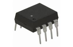
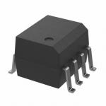
HCNW2201 Electronic IC Chips Logic Gate Optocouplers
|
|
Stock Offer (Hot Sell)
Very High CMR, Wide VCC Logic Gate Optocouplers
Features • 10 kV/µs Minimum Common Mode Rejection (CMR) at VCM = 1000 V (HCPL-2211/2212/0211/ 2232, HCNW2211) • Wide Operating VCC Range: 4.5 to 20 Volts • 300 ns Propagation Delay Guaranteed over the Full Temperature Range • 5 Mbd Typical Signal Rate
• Low Input Current (1.6 mA to 1.8 mA) • Hysteresis • Totem Pole Output (No Pullup Resistor Required) • Available in 8-Pin DIP, SOIC-8, Widebody Packages • Guaranteed Performance from -40°C to 85°C
• Safety Approval UL Recognized -2500 V rms for 1 minute (5000 V rms for 1 minute for HCNW22XX) per UL1577 CSA Approved VDE 0884 Approved with VIORM = 630 V peak (HCPL- 2211/2212 Option 060 only) and VIORM = 1414 V peak (HCNW22XX only) BSI Certified (HCNW22XX only) • MIL-STD-1772 Version Available (HCPL-52XX/62XX)
Applications • Isolation of High Speed Logic Systems • Computer-Peripheral Interfaces • Microprocessor System Interfaces
• Ground Loop Elimination • Pulse Transformer Replacement • High Speed Line Receiver • Power Control Systems
Description The HCPL-22XX, HCPL-02XX, and HCNW22XX are opticallycoupled logic gates. The HCPL-22XX, and HCPL-02XX contain a GaAsP LED while the HCNW22XX contains an AlGaAs LED. The detectors have totem pole output stages and optical receiver input stages with built-in Schmitt triggers to provide logiccompatible waveforms, eliminating the need for additional waveshaping.
A superior internal shield on the HCPL-2211/12, HCPL-0211, HCPL-2232 and HCNW2211 guarantees common mode transient immunity of 10 kV/µs at a common mode voltage of 1000 volts.
The electrical and switching characteristics of the HCPL- 22XX, HCPL-02XX and HCNW22XX are guaranteed from -40°C to +85°C and a VCC from 4.5 volts to 20 volts. Low IF and wide VCC range allow compatibility with TTL, LSTTL, and CMOS logic and result in lower power consumption compared to other high speed couplers. Logic signals are transmitted with a typical propagation delay of 150 ns.
Absolute Maximum Ratings
Notes: 1. Each channel. 2. Derate total package power dissipation, PT, linearly above 70°C free-air temperature at a rate of 4.5 mW/°C.
Functional Diagram
|
|||||||||||||||||||||||||||||||||||||||||||||||||||||||||||||||||||||||||||||||||||||||||||||||||||||||||||||||||||||||||||||||||||||||||||||||||||||||||||||||||||||||||||||||||||||||||||||||||||||||||||||||||||||||||||||||||||||||||||
| Product Tags: electronic integrated circuit linear integrated circuits | |||||||||||||||||||||||||||||||||||||||||||||||||||||||||||||||||||||||||||||||||||||||||||||||||||||||||||||||||||||||||||||||||||||||||||||||||||||||||||||||||||||||||||||||||||||||||||||||||||||||||||||||||||||||||||||||||||||||||||
|
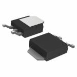
RB450FT106 Rectifier Diode Schottky barrier diode diode laser hair removal |
|
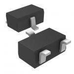
TK10P60W Power Mosfet Transistor MOSFETs Silicon N-Channel MOS |
|
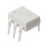
4N25M Electronic IC Chips General Purpose Phototransistor Optocouplers |
|
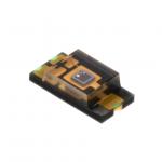
TEMT6000X01 Electronic IC Chips Ambient Light Sensor, RoHS Compliant |
|
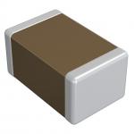
GRM033R71C272KA88D NEW AND ORIGINAL STOCK |
|
FOD2742B Flash Memory IC NEW AND ORIGINAL STOCK |