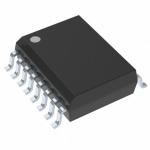
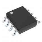
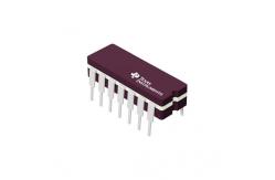
Transistor Integrated Circuit Chip SN74HC74N Positive Edge Triggered Flip Flops
|
|
Transistor Integrated Circuit Chip SN74HC74N Positive Edge Triggered Flip Flops
SN74HC74N Dual D-Type Positive-Edge-Triggered Flip-Flops With Clear And Preset
Wide Operating Voltage Range of 2 V to 6 V Outputs Can Drive Up To 10 LSTTL Loads Low Power Consumption, 40-µA Max ICC Typical tpd = 15 ns ±4-mA Output Drive at 5 V Low Input Current of 1 µA Max
description/ordering information The ’HC74 devices contain two independent D-type positive-edge-triggered flip-flops. A low level at the preset (PRE) or clear (CLR) inputs sets or resets the outputs, regardless of the levels of the other inputs. When PRE and CLR are inactive (high), data at the data (D) input meeting the setup time requirements are transferred to the outputs on the positive-going edge of the clock (CLK) pulse. Clock triggering occurs at a voltage level and is not directly related to the rise time of CLK. Following the hold-time interval, data at the D input can be changed without affecting the levels at the outputs. absolute maximum ratings over operating free-air temperature range (unless otherwise noted)‡ Supply voltage range, VCC –0.5 V to 7 V Input clamp current, IIK (VI < 0 or VI > VCC) (see Note 1) ±20 mA Output clamp current, IOK (VO < 0 or VO > VCC) (see Note 1) ±20 mA Continuous output current, IO (VO = 0 to VCC) ±25 mA Continuous current through VCC or GND ±50 mA Package thermal impedance, θJA (see Note 2): D package 86 . . . . . . . . . . . . . . . . . . . . . . . . . . . . . . . . . . . °C/W DB package 96 . . . . . . . . . . . . . . . . . . . . . . . . . . . . . . . . . °C/W N package 80 . . . . . . . . . . . . . . . . . . . . . . . . . . . . . . . . . . . °C/W NS package 76 . . . . . . . . . . . . . . . . . . . . . . . . . . . °C/W PW package 113 °C/W Storage temperature range, Tstg . . . . . . . . . . . . . . . . . . . . . . . –65°C to 150°C
PARAMETER MEASUREMENT INFORMATION
NOTES: A. CL includes probe and test-fixture capacitance. B. Phase relationships between waveforms were chosen arbitrarily. All input pulses are supplied by generators having the following characteristics: PRR ≤ 1 MHz, ZO = 50 Ω, tr = 6 ns, tf = 6 ns. C. For clock inputs, fmax is measured when the input duty cycle is 50%. D. The outputs are measured one at a time with one input transition per measurement. E. tPLH and tPHL are the same as tpd.
ORDERING INFORMATION
|
||||||||||||||||||||||||||||||||||||
| Product Tags: small scale integrated circuits integrated components | ||||||||||||||||||||||||||||||||||||