
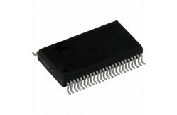
SN74LVTH16245ADGGR Programmable Logic ICS Bus Transceivers Tri-State ABT 16-Bit
|
|
SN74LVTH16245ADGGR Programmable Logic ICS Bus Transceivers Tri-State ABT 16-Bit
FEATURES • Members of the Texas Instruments WidebusTM Family • State-of-the-Art Advanced BiCMOS Technology (ABT) Design for 3.3-V Operation and Low Static-Power Dissipation • Support Mixed-Mode Signal Operation (5-V Input and Output Voltages With 3.3-V VCC) • Support Unregulated Battery Operation Down to 2.7 V • Typical VOLP (Output Ground Bounce) <0.8 V atVCC =3.3V,TA =25°C High-Speed Switching Noise 1B7 • Flow-Through Architecture Optimizes PCB 1B8 • Ioff and Power-Up 3-State Support Hot Insertion • Bus Hold on Data Inputs Eliminates the Need for External Pullup/Pulldown Resistors • Latch-Up Performance Exceeds 500 mA Per JESD 17 • ESD Protection Exceeds JESD 22 – 200-V Machine Model (A115-A)
DESCRIPTION/ORDERING INFORMATION The 'LVTH16245A devices are 16-bit (dual-octal) noninverting 3-state transceivers designed for low-voltage (3.3-V) VCC operation, but with the capability to provide a TTL interface to a 5-V system environment. The devices are designed for asynchronous communication between two data buses. The logic levels of the direction-control (DIR) input and the output-enable (OE) input activate either the B-port outputs or the A-port outputs or place both output ports into the high-impedance mode. The device transmits data from the A bus to the B bus when the B-port outputs are activated, and from the B bus to the A bus when the A-port outputs are activated. The input circuitry on both A and B ports is always active and must have a logic HIGH or LOW level applied to prevent excess ICC and ICCZ. Active bus-hold circuitry holds unused or undriven inputs at a valid logic state. Use of pullup or pulldown resistors with the bus-hold circuitry is not recommended. When VCC is between 0 and 1.5 V, the devices are in the high-impedance state during power up or power down. However, to ensure the high-impedance state above 1.5 V, OE should be tied to VCC through a pullup resistor; the minimum value of the resistor is determined by the current-sinking capability of the driver. These devices are fully specified for hot-insertion applications using Ioff and power-up 3-state. The Ioff circuitry disables the outputs, preventing damaging current backflow through the devices when they are powered down. The power-up 3-state circuitry places the outputs in the high-impedance state during power up and power down, which prevents driver conflict. |
|
24AA1025-I/SM Programmable IC Chips 1024K I2C™ CMOS Serial EEPROM |
|
SST26VF032B-104I/MF FLASH Memory IC 32Mbit SPI - Quad I/O 104 MHz 8-WDFN (5x6) |

|
SST26VF032B-104I/MF Flash Memory Chip IC Micro 32 Mbit Low Power Consumption |
|
LPC1768FBD100K MCU Chips IC MCU 32BIT 512KB FLASH 100LQFP 32 BIT Micro Controllers |

|
EPCS16SI8N NEW AND ORIGINAL STOCK |
|
Professional Flash Memory Products Ic Memory Chip XCF08PVOG48C |