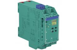
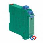
Rotation Speed Monitor KFA6-DWB-Ex1.D 1-channel isolated barrier, 230 V AC supply, Dry contact or NAMUR
inputs, Input frequency 1 mHz ... 5 kHz, 2 relay contact outputs,
Start-up override, Configurable by keypad, Line fault detection
(LFD), Up to SIL 2 acc. to IEC/EN 61508 / IEC/EN 61511, Housing
width: 40 mm, Number of channels: 1-channel, Trip relay, Start-up
override, Rotation speed monitoring, Safety Integrity Level (SIL):
SIL 2, Rated voltage: 230 V AC ± 10 %, Field device: NAMUR sensor,
Field device [2]: volt-free contact Technical Data General specifications |
|---|
Signal type | Digital Input | Functional safety related parameters |
|---|
Safety Integrity Level (SIL) | SIL 2 | Supply |
|---|
Connection | terminals 23, 24 | Rated voltage | 230 V AC ± 10 % | Rated current | 18 mA | Power dissipation/power consumption | ≤ 2 VA / 2 VA | Input |
|---|
Connection side | field side | Connection | Input I: intrinsically safe: terminals 1+, 3-
Input II: non-intrinsically safe: terminals 13+, 14- | Input I | acc. to EN 60947-5-6 (NAMUR) | | Pulse duration | > 50 µs | | Input frequency | 0.001 ... 5000 Hz | | Line fault detection | breakage I ≤ 0.15 mA; short-circuit I > 6.5 mA | Input II | startup override: 1 ... 1000 s, adjustable in steps of 1 s | | Active/Passive | I > 4 mA (for min. 100 ms)/ I < 1 mA | | Open circuit voltage/short-circuit current | 18 V / 5 mA | Output |
|---|
Connection side | control side | Connection | output I: terminals 10, 11, 12
output II: terminals 16, 17, 18 | Output I, II | signal, relay | | Contact loading | 253 V AC / 2 A / cos φ ≥ 0.7 ; 40 V DC / 2 A | | Mechanical life | 5 x 10⁷ switching cycles | | Energized/De-energized delay | approx. 20 ms / approx. 20 ms | Transfer characteristics |
|---|
Input I | | | Measurement range | 0.001 ... 5000 Hz | | Resolution | 0.1 % of measured value , ≥ 0.001 Hz | | Accuracy | 0.1 % of measured value , > 0.001 Hz | | Measuring time | < 100 ms | | Influence of ambient temperature | 0.003 %/K (30 ppm) | Output I, II | | | Response delay | ≤ 200 ms | Galvanic isolation |
|---|
Input I/other circuits | reinforced insulation according to IEC/EN 61010-1, rated insulation
voltage 300 Veff | Output I, II against eachother | reinforced insulation according to IEC/EN 61010-1, rated insulation
voltage 300 Veff | Output I, II/other circuits | reinforced insulation according to IEC/EN 61010-1, rated insulation
voltage 300 Veff | Start-up override/power supply | reinforced insulation according to IEC/EN 61010-1, rated insulation
voltage 300 Veff | Indicators/settings |
|---|
Display elements | LEDs , display | Control elements | Control panel | Configuration | via operating buttons | Labeling | space for labeling at the front | Directive conformity |
|---|
Electromagnetic compatibility | | | Directive 2014/30/EU | EN 61326-1:2013 (industrial locations) | Low voltage | | | Directive 2014/35/EU | EN 61010-1:2010 | Conformity |
|---|
Electromagnetic compatibility | NE 21:2006 | Degree of protection | IEC 60529:2001 | Ambient conditions |
|---|
Ambient temperature | -20 ... 60 °C (-4 ... 140 °F) | Mechanical specifications |
|---|
Degree of protection | IP20 | Connection | screw terminals | Mass | 300 g | Dimensions | 40 x 119 x 115 mm (1.6 x 4.7 x 4.5 inch) (W x H x D) , housing type
C2 | | Height | 119 mm | | Width | 40 mm | | Depth | 115 mm | Mounting | on 35 mm DIN mounting rail acc. to EN 60715:2001 | Data for application in connection with hazardous areas |
|---|
EU-type examination certificate | TÜV 99 ATEX 1408 | | Marking | II (1)G [Ex ia Ga] IIC
II (1)D [Ex ia Da] IIIC
I (M1) [Ex ia Ma] I | Supply | | | Maximum safe voltage | 253 V AC (Attention! Um is no rated voltage.) | Input I | terminals 1+, 3-: Ex ia | | Voltage Uo | 10.1 V | | Current Io | 13.5 mA | | Power Po | 34 mW (linear characteristic) | Input II | terminals 13+, 14- non-intrinsically safe | | Maximum safe voltage Um | 40 V (Attention! The rated voltage can be lower.) | Output I, II | terminals 10, 11, 12; 16, 17, 18 non-intrinsically safe | | Maximum safe voltage | 253 V (Attention! The rated voltage can be lower.) | | Contact loading | 253 V AC/2 A/cos φ > 0.7; 40 V DC/2 A resistive load | Certificate | TÜV 02 ATEX 1885 X | | Marking | II 3G Ex nA nC IIC T4 Gc | Output I, II | | | Contact loading | 50 V AC/2 A/cos φ > 0.7; 40 V DC/2 A resistive load | Galvanic isolation | | | Input I/other circuits | safe electrical isolation acc. to IEC/EN 60079-11, voltage peak
value 375 V | Directive conformity | | | Directive 2014/34/EU | EN 60079-0:2012+A11:2013 , EN 60079-11:2012 , EN 60079-15:2010 | International approvals |
|---|
FM approval | | | Control drawing | 16-538FM-12 | UL approval | E223772 | IECEx approval | | | IECEx certificate | IECEx TUN 03.0000 | | IECEx marking | [Ex ia Ga] IIC , [Ex ia Da] IIIC , [Ex ia Ma] I |
Related Models: KFU8-UFT | KFD0-CS-Ex1.51P | NBB8-18GM50-A2-V1 | K-HM26-2M-261533 | KFD0-CS-Ex2.50P | NBB8-18GM50-E0 | NBB15-U1-E2 | KFD0-CS-Ex2.51P | NBB8-18GM50-E0-V1 | NBB1,5-5GM25-E2 | KFD0-RO-Ex2 | NBB8-18GM50-E2 | NBB1,5-5GM25-E2-V3 | KFD0-SCS-Ex1.55 | NBB8-18GM50-E2-V1 | NBB1,5-F79-E0 | KFD0-SD2-Ex2.1045 | NBB8-18GM50-E2-V1-M | NBB1,5-F79-E2 | KFD0-SD2-Ex2.1245 | NBB8-18GM60-A2-V1 | NBB15-U1-Z2 | KFD0-TR-Ex1 | NBB8-18GM60-US | NBB5-18GM50-E2-V1 | KFD0-CC-1 | NBN3-8GM40-E2-V3 | NBB15-30GM30-E2-V1 | KFD0-HMS-16 | NBN3-F25F-E8-V1 | NBB15-30GM50-A2-V1 | KFD0-RSH-1.4S.PS2 | NBN40-U1K-N0 | NBB15-30GM50-E2 | KFD0-SD2-EX1.10100 | NBN40-U4LK-N0 | NBB15-30GM50-E2-M | KFD0-SD2-EX1.1045 | NBVB15-U1.Z2 | NBB15-30GM50-E2-V1 | KFD2-UT2-1 | NCB5-18GM40-NO | NBB15-30GM50-E2-V1-M | KFD2-CD-1.32 | NJ10-30GM-N-5M | NBB8-18GM30-E2 | KFD2-CD-EX1.32 | NJ15-30GK-N | NBB8-18GM30-E2-V1 | KFD2-HMM-16 | NJ2-12GK-SN | NBB8-18GM60-A2-V1 | KFD2-SH-EX1.T | NJ2-12GM-N | NJ4-12GK-SN | KFD2-UT2-1 | RD0-FB-EX4.COM | NJ5-18GK-N | KFD2-VR4-EX1.26 | SC3,5-G-N0 | NJ5-18GK-N-150 | KFU8-UFC-1.D | SC3,5-G-N0-5M | NJ5-18GM-N | V15-G-2M | SC3,5-G-N0-6M | NJ8-18GK-N | Z 787 | SJ3,5-N | RD0-FB-EX4 | Z787.H | SJ3,5-S1N | RD0-TI-Ex8.FF.* | HIC2031 | UPR-03 | Z787.F | Z787.H.F | SJ3,5-N-BU |
|