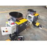
Head & Tail positionerIt is composed by Head, Tail, replace system, travel system, lock
system, basement, jaws and control system. - 1)Head
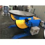
The head is composed by jaws, rotate table, slew bearing, cycloid
reducer, electric device, switches and body base. Rotate progress
is: motor with brake—cycloid reducer—output gear—slew
bearing—table. Rotate speed is around 1rpm, stationary. Stop has
self lock function, that means when load on the component, and
eccentric is inside stipulated range, the working table will not
rotate by self. Eccentric distance is related to load capacity.
When load much, the distance is small. - 2)Tail
The tail is composed by jaws, rotate table, rotate shaft, auto
replace device, switches and body base. The rotation of tail is
driven by the table on head. The table and jaws on tail is for
supporting and assitance. And there is replace device on table.
Working theory is: when load on component, push “replace” on
control board, clutch on, reducer drives wheel rotating, through
chain, the table rotate. There is limited block at backside of
table, when close to limited switch, the table stops automatically.
Then load on the component. After loading, push again “replace”,
clutch off, then the table rotate together with the table on Head. - 3)Travel
and lock system By pushing the tail on basement to suitable for
different size component. After reaching a desired place, lock the
tail. The lock system is lead screw and nut. - 4)Jaws
The jaws are designed as per different components. There are
component no. on each set of jaws, and they are indicated also at
relative channels. Then operators can easily find suitable jaws
when load on different components. - 5)Control system
All the control pushbuttons are on control cabinet, with rotate
forward, rotate backward, rotate stop. And there is a remote box
for easy operation. - 6)Conduction of welding current
The welding current is conducted by three sets of electrical
devices through cables to basement, allowing 1000A welding current.
|