Analog Video Transmitter (VTX) Signal Anti-interference Capability Core Positioning Core Positioning
An analog video transmitter (VTX) with exceptional signal
anti-interference capability, ensuring stable, clear, and
low-latency video transmission in complex electromagnetic
environments through optimized RF design and intelligent channel
management. It serves as a solution for professional FPV flight and
high-reliability visual applications. Application Scenarios - Racing and Freestyle FPV Flight: Maintains stable, snow-free video feeds in competitive
environments with multiple simultaneous devices and overlapping
signals.
- Urban and Indoor Flight: Handles dense wireless signal interference from Wi-Fi, Bluetooth,
and other sources, ensuring usable video after penetrating walls or
navigating obstacles.
- Industrial Inspection and Security Monitoring: Maintains reliable video links in industrial settings with strong
electromagnetic noise from motors, inverters, and other equipment.
- Drone Formations and Performances: Prevents video loss due to same-channel or adjacent-channel
interference in ultra-dense transmitter environments.
Core Selling Points - Multi-Dimensional Anti-Interference Design: Utilizes hardware enhancements such as high-frequency filtering,
linear power amplifiers, and shielded enclosures, combined with
intelligent power control and channel optimization algorithms to
improve interference resistance from both physical and logical
layers.
- Adaptive Channel Cleaning Technology: Monitors ambient spectral noise in real time, automatically
selecting or recommending the optimal channel to avoid congested
frequency bands and ensure a clean video feed.
- Strong Interference Resilience: Significantly reduces visual artifacts such as snow, smearing,
and tearing under equivalent signal strength compared to
conventional VTXs, enhancing visual continuity.
- Compatibility and Ease of Use: Supports standard video input and power interfaces for seamless
integration into existing FPV systems, with interference status
indicated via LED or OSD prompts.
Product Specifications | Project | Specifications |
|---|
| Working voltage : | DC 7-20V | | Working current : | 2.6A@12V | | Operating ambient temperature : | -10~65℃ | | Weight : | 70g (excluding the antenna) | | Outline dimension : | 74mm*38.5mm*24mm | | Mounting hole position: | 20mm x 20mm spacing, with M2 threaded holes included | | Number of channels: | 88CH | | Frequency range : | 4900~6100MHz | | Output power : | 25mW ,500mW , 1W,5W,10W | | Control protocol : | IRC Tramp supports OSD parameter adjustment | | Modulation type: | FM frequency modulation | | Channel bandwidth : | 8MHz | | Antenna interface: | SMA (external thread with internal hole) | | Video format: | NTSC/PAL |
Product Features | Supports operation across the 4.9G to 6.1G broadband spectrum | | Button/IRC control for quick CH and power adjustment | | Special design eliminates antenna connection and power amplifier
burnout | | Automotive-grade RF crystal with temperature range and enhanced
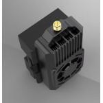
frequency stability | | Fully metal CNC casing with dustproof and explosion-proof features,
excellent heat dissipation, and stable power output | | Fast frequency locking, no interference with peers during startup | | High-temperature protection: When the product overheats during
continuous operation, the image transmission system activates power
reduction protection. Once the system reaches the equilibrium
point, power output gradually increases to prevent thermal damage
from high temperatures. | | High output power, stable output power, and long transmission
distance |
Interface Function Definition | joggle | functional description |
|---|
| GND1,GND2: | The ground wire connects to the GND of the flight control system. | | RX: | Image transmission control signal input: Connect to the UART TX
interface of devices such as flight control systems, and activate
the IRC control protocol to regulate functions including
transmission frequency, bandwidth, and power. | | VTX: | Video input: Connect to the flight control's video output (VTX) | | VCC: | Connect the DC 7V-20V power input to the positive terminal of the
DC-DC buck regulator module, not directly to the flight controller. | | GND: | Connect the negative terminal of the power input to the negative
terminal of the DC-DC buck regulator module. | | POWER: | power adjustment button - Short press to adjust power, cycling between five levels: 25mW,
500mW, 1W,5W, and 10W.
- Double-click to enter PIT mode (Maintenance Mode, with minimal
video output power; avoid activation if possible).
- Long press to lock/unlock the image transmission power and
frequency buttons (to prevent accidental touches)
| | FRCH: | Frequency/Channel Adjustment Button - Short press to change channel, cycling between CH1 to CH8
- Long press for 3 seconds to enter frequency group switching mode.
Short press again to change the frequency group.
| | PWR LED: | Power indicator: Red (flashes to indicate power level) - Red light off: indicates entry into PIT mode
- Red light on: Locks the video transmission power and frequency
buttons
| | CH LED: | Channel indicator: Green (indicates channel CH by the number of
flashes) | | FR LED: | Band indicator light: Blue (indicates the number of flashes for the
band) |
Frequency Table 1. Power and LED status (PWR LED flash count) | Red LED flashing in a loop | extinct | Always on | Flash once | Flash twice | Flash 3 times | Flash 4 times | Flash 5 times |
|---|
| Power level | PIT | Lock button | 25mW | 500mW | 1W | 5W | 10W |
2. Frequency group, channel, and indicator light status (LED flash
count) Frequency group indicator (blue)
FR LED Flashing Indicator | Channel (MHz)
Indicator light (green LED) |
|---|
CH1 Flash once | CH2 Flash twice | CH3 Flash 3 times | CH4 Flash 4 times | CH5 Flash 5 times | CH6 Flash 6 times | CH7 Flash 7 times | CH8 Flash 8 times |
|---|
| LED flash once | Band A | 5856 | 5845 | 5825 | 5805 | 5785 | 5765 | 5745 | 5725 | | LED flashes twice | Band B | 5733 | 5752 | 5771 | 5790 | 5809 | 5828 | 5847 | 5866 | | LED flashes 3 times | Band E | 5705 | 5685 | 5665 | 5645 | 5885 | 5905 | 5925 | 5945 | | LED flashes 4 times | Band F | 5740 | 5760 | 5780 | 5800 | 5820 | 5840 | 5860 | 5880 | | LED flashes 5 times | Band R | 5658 | 5695 | 5732 | 5769 | 5806 | 5843 | 5880 | 5917 | | LED flashes 6 times | Band H | 5653 | 5693 | 5733 | 5773 | 5813 | 5853 | 5893 | 5933 | | LED flashes 7 times | Band L | 5333 | 5373 | 5413 | 5453 | 5493 | 5533 | 5573 | 5613 | | LED flashes 8 times | Band U | 5325 | 5348 | 5366 | 5384 | 5402 | 5420 | 5438 | 5456 | | LED flashes 9 times | Band O | 5474 | 5492 | 5510 | 5528 | 5546 | 5564 | 5582 | 5600 | | LED flashes 10 times | Band X | 4990 | 5020 | 5050 | 5080 | 5110 | 5140 | 5170 | 5200 | | The LED flashes 11 times. | Band Z | 6002 | 6028 | 6054 | 6080 | 6106 | 6132 | 6158 | 6184 |
Installation dimension drawing Notes: If the RX cable is already connected to the transmitter of the
flight controller, the buttons will not function. Details of Accessories (Attached Diagram) Terminal wire 4P terminal wire, length 200mm ±3mm | | power line 2P terminal wire, length 200mm ±3mm | | Bamboo stick antenna 5.8G frequency band, with an intermediate connecting cable
measuring 140mm ± 3mm | |
Company Information Shenzhen Fengqing Instrument Co., Ltd. Crafted in China, Quality Forges Low-Altitude Security.
Upholding a "customer-first" philosophy, Fengqing Instrument is
committed to providing professional service throughout the entire
product lifecycle: - Pre-sales Consultation: Customized solution designs and product recommendations based on
client needs.
- In-sales Support: Comprehensive technical support for installation, debugging, and
operational training.
- After-sales Service: Rapid-response system including remote support and on-site
maintenance.
|