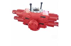
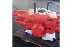
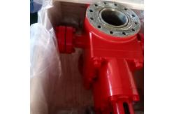
Introduction to Simplified U-type Ram Blowout Preventer (Simplified
U-type Ram BOP) The Simplified U-type Ram Blowout Preventer is a key well control
equipment in oil and gas drilling, workover, and well testing
operations. Specifically designed for wellbore pressure control and
blowout prevention, it provides reliable safety guarantees for
various downhole operations through its robust structure, precise
hydraulic drive, and wide adaptability. Core Features - Full Forged Structure for Durability: Core components such as the
BOP body, bonnets, and ram blocks are forged from high-strength
alloy steel, reinforced by heat treatment, and exhibit excellent
impact and high-pressure resistance. The rams adopt a forged U-type
design with outstanding strength and toughness, adapting to sealing
and shearing requirements under complex working conditions.
- Wide Range of Bore Sizes and Pressure Ratings: Bore size
specifications include 7 1/16", 9", 11", 13 5/8", 16 3/4", 18 3/4",
20 3/4", 21 1/4", 26 3/4", etc., matching different wellbore and
string sizes. The rated working pressure ranges from 2000psi
(13.8MPa) to 15000psi (103.4MPa), meeting medium-high to
high-pressure operation requirements.
- Precise Oil Passage-Driven Bonnet Design: The bonnets feature a
hinge-free structure, fully controlled by the linkage between
hydraulic oil passages and opening/closing piston rods. The core
logic is "opening the rams closes the bonnets, and closing the rams
opens the bonnets". When opening, high-pressure oil (8.4~10.5MPa)
is injected into the BOP's closing oil passage hole, which enters
the opening/closing piston rod to push the bonnets to sliding open.
When closing, high-pressure oil is injected into the opening oil
passage, driving the bonnets to sliding close and fit the body. The
operation is precise and labor-saving.
- Dual Protection for Sealing Performance: Initial sealing is formed
through four key sealing points (ram top seal with body, front seal
with string/itself, body with bonnet, and ram shaft with bonnet).
Downhole pressure can push the rams to fit the sealing surface
furtherly, achieving pressure-assisted sealing. Equipped with a
secondary sealing mechanism, emergency remediation can be performed
by grease injection when the sealing ring is damaged, avoiding
leakage escalation.
- Strong Functional Adaptability: Compatible with various ram types
including pipe rams, blind rams, shear rams, and variable-bore
rams, it can realize functions such as annular space sealing, full
wellbore sealing, and emergency string shearing. Some models
support tripping operations. The rams are compatible with standard
tubing, drill pipes, drill collars, and other downhole tools,
meeting multi-scenario operation requirements.
- Corrosion Resistance, Compliance, and Easy Maintenance: Metal
components in contact with well fluid undergo anti-corrosion
treatment, and flanges and sealing surfaces are overlay-welded with
stainless steel, complying with NACE MR-0175 standard for sulfide
stress cracking resistance. The hydraulic oil circuit adopts a
body-embedded design to avoid external damage. The bonnets are
hydraulically driven to sliding open, enabling quick access to
wearing parts for on-site replacement with high efficiency,
reducing downtime significantly.
Opening Methods and Bonnet Operation - Ram Opening Methods
- Hydraulic Direct Opening: When manual locking is not activated,
inject 8.4~10.5MPa high-pressure oil into the ram opening cavity
through the hydraulic control system to push the piston, driving
the ram shaft and ram assembly away from the wellhead center, and
quickly opening the wellbore (simultaneously closing the bonnets).
- Hydraulic Opening After Manual Unlocking: When the ram is locked by
the manual locking device, first rotate the handwheel
counterclockwise to drive the locking shaft to the end, then turn
back 1/8~1/4 turn to prevent jamming due to temperature changes.
Subsequently, supply pressure to the opening cavity to drive the
ram to open (simultaneously closing the bonnets). This is the only
effective way to unlock the locked ram.
- Bonnet Opening Operation (Requires Closing the Rams)
First, loosen the bonnet fixing bolts, then inject hydraulic oil
into the BOP's closing oil passage hole. The hydraulic oil enters
the opening/closing piston rod, pushing the bonnets to slide and
separate from the body, exposing the ram cavity for maintenance
operations. - Bonnet Closing Operation (Requires Opening the Rams)
Inject hydraulic oil into the BOP's opening oil passage, which
enters the opening/closing piston rod to push the bonnets to slide
and reset to fit the body sealing surface. After confirming proper
fitting, evenly tighten the bonnet fixing bolts to complete sealing
and fixing. Wellhead Installation and Inspection Pre-Installation Inspection - Verify the BOP's pressure test qualification certificate, confirm
that the ram specifications match the downhole drilling tool size,
and ensure the sealing rubber packer is free of damage and aging.
Check that the sealing ring grooves of the wellhead flange and BOP
flange are intact, free of protrusions, scratches, and other
defects, and clean impurities on the flange surface. - Field Test: Fill the BOP with water, test opening and closing the
rams once to verify the linkage logic of “opening the rams closes
the bonnets, and closing the rams opens the bonnets”. Test the
bonnet translation function to ensure consistency between oil
passage injection and bonnet movement without jamming.
Wellhead Installation Steps - Flange Connection: Apply thread grease meeting ISO 13678
requirements to the bolts, and tighten them evenly diagonally in
three stages (50% torque for the first time, 100% for the second
time, and re-tightening for the third time). The torque must comply
with the corresponding specification requirements.
- Pipeline and Component Connection: Connect the hydraulic control
pipelines, clearly mark the "opening/closing oil passages"
corresponding to ram operation and bonnet drive to ensure
consistency with the indication of master control unit. Connect the
manual operating lever to ensure flexible operation of the manual
locking mechanism. Install kill and choke manifolds to ensure tight
sealing of interfaces.
Post-Installation Inspection - Confirm the BOP is installed in the correct direction (lifting lugs
at the top), and all bolts are properly tightened without
loosening.
- Test the linkage between rams and bonnets with a control pressure
of 2~3MPa: the bonnets should open synchronously when closing the
rams, and close synchronously when opening the rams. Verify
consistency between the indication of master control unit and
actual movements.
- Test the manual locking mechanism, record the number of handwheel
rotations during well closing and mark it with a tag. After the
test, unlock and hydraulically open the rams (bonnets close
synchronously).
- Conduct a full-system pressure test on the wellhead equipment, with
the test pressure meeting operation requirements. Re-tighten all
connecting bolts after the pressure test. Recheck the bonnet
sealing condition to ensure no leakage.
Usage Methods - Specialized Operation and Management: Assign personnel with "Three
Understandings and Four Capabilities" (understand principles,
performance, and processes; be able to operate, maintain, service,
and troubleshoot faults) to be responsible for the BOP.
Unauthorized personnel are prohibited from operating it. Focus on
mastering the operation logic of oil passages corresponding to
bonnets/rams.
- Standardized Operating Pressure: When there is no string in the
well, the hydraulic control pressure for testing the closing of
pipe rams shall not exceed 3MPa. When there is a string in the
well, it is strictly prohibited to close the blind rams and shear
rams.
- Use of Manual Locking: For long-term well sealing, first
hydraulically close the rams (bonnets open synchronously), then
lock the rams with the manual locking device, and place a warning
tag on the master control unit and control panel to prevent
misoperation.
- Regular Maintenance and Inspection: After entering the target zone,
test the linkage function between rams and bonnets daily. Conduct a
blind ram opening/closing test after each tripping operation (when
there is no string in the well). Regularly check the
opening/closing piston rods, oil passage smoothness, and sealing
condition, and replace aging rubber packers as required.
- Fault Handling: In case of abnormal linkage between rams and
bonnets or sealing leakage, first relieve pressure and identify the
cause (such as oil passage blockage, piston rod jamming, or sealing
ring damage). It is strictly prohibited to disassemble the bonnets
or force operation under pressure to avoid component damage.
| Model | Single Ram | Double Ram |
|---|
| Top Connection | Flanged | Flanged | | Bottom Connection | Flanged | Flanged | | Weight(kg) | 496 | 898 | | Height H(mm) | 556 | 778 | | Well Bore | 179.4mm(7 1/16″) | | Hydrostatic Test Pressure | 31.1MPa(4,500psi) | | Rated Working Pressure | 20.7MPa(3,000psi) | | Hydraulic Control System Hydrostatic Test Pressure | 31.1MPa(4,500psi) | | Hydraulic Control System Rated Working Pressure | 20.7MPa(3,000psi) | | Recommended Hydraulic Operating Pressure | 8.3-10.4MPa(1,200-1,500psi) | | Volume of Open One Set of Ram Assembly | 2.9 L | | Volume of Close One Set of Ram Assembly | 3.3 L | | Hydraulic Control Line Interface Thread | NPT 1″ | | Side Outlets | 2 1/16"-5,000psi/(or follow the contract requirement) | | Metallic material temperature class | T-20/250 (-29~121℃) or follow the contract | | Non-metallic material temperature class | BGB (-18~93℃) or follow the contract | | BOP performance class | PR1 | illustrate: The design and manufacture of BOP conform to API Spec 16A. The part of the BOP in contact with the well fluid is resistant to
hydrogen sulfide stress corrosion and meets the requirements of
NACE MR 0175. |
|