Micro-Controlled 3 Cubic Meter Room Wire And Cable Smoke Density
Tester
Product Introduce
IEC 61034 is a standard developed by the International
Electrotechnical Commission for evaluating the smoke density
generated by wires, cables and optical cables under specific
burning conditions. It is divided into IEC 61034-1 (test equipment
specifications) and IEC 61034-2 (test procedures and requirements).
The standard quantifies the smoke density by burning the cable
sample with a 1 liter standard alcohol fire source in a 3m × 3m ×
3m test chamber and measuring the beam transmittance. The test is
applicable to low-smoke halogen-free cables, building cables, and
cables for railways, ships and other scenarios, and is designed to
verify their impact on visibility and escape safety in fires. The
results support CE mark certification and European CPR regulatory
requirements, ensuring the fire performance of cables in
high-safety environments.
Standard
IEC 61034-1:2005
Title: Measurement of smoke density of cables burning under defined
conditions – Part 1: Test apparatus
Content: Detailed requirements for test equipment used to measure
smoke emissions from burning wires, cables or optical cables under
defined conditions. Includes technical specifications for test
chambers, photovoltaic systems, light sources and other auxiliary
equipment.
IEC 61034-2:2005
Title: Measurement of smoke density of cables burning under defined
conditions – Part 2: Test procedure and requirements
Content: Specifies test procedures and requirements, including
preparation and installation of cable samples, burning methods, and
evaluation criteria for test results. Describes how to evaluate
smoke density by measuring the transmittance of a light beam
through smoke.
Test product scope
IEC 61034 applies to the following products:
Wires and cables: All insulated metal conductor cables used for
energy or signal transmission.
Fiber optic cables: Smoke density test of optical cables under
specific combustion conditions.
Halogen-free cables and materials: Special attention is paid to
low-smoke halogen-free (LSZH) cables, which are widely used in
scenes with high smoke emission requirements such as construction,
railways and ships.
Other related materials: Plastic materials (such as PVC, LSZH) used
for cable insulation or sheathing need to be evaluated for their
smoke generation potential during combustion.
Main prameter
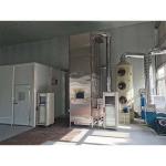
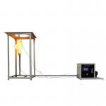
1 This test machine is designed according to Part 1 (Test
Equipment) and Part 2 (Test Procedures and Requirements) of the
IEC61034 standard. The optical measurement system for the smoke
density of cables or optical cables burning under specific
conditions consists of a light source, a silicon photocell receiver
and a computer system. The light generated by the light source
passes through a 3m×3m×3m smoke density laboratory, forming a
uniform beam with a diameter of 1.5m±0.1m on the wall opposite the
light source. The photocell installed at the center of the beam
detects the intensity of the beam from the light source. When a
large amount of smoke is generated in the combustion chamber due to
the burning of cables or optical cables, the smoke absorbs part of
the photoelectricity, and the intensity of the beam reaching the
silicon photocell is weakened. By processing the data through the
computer system, the transmittance It with a linear response
relative to the initial 100% can be calculated.
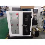
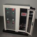
2 This instrument involves professional knowledge in three aspects:
mechanics, optics, and electronics. It is a
mechanical-optical-electrical integrated product with the
advantages of reasonable structure, stable performance, and easy
operation; WINDOWS XP operation interface, LabVIEW style, and
perfect safety mechanism. During the test, the measurement results
are displayed in real time and a perfect curve is dynamically
drawn. The data can be permanently saved, retrieved and printed
out, and reports can be printed directly.
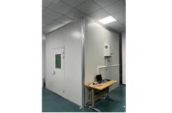
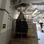
Combustion chamber:
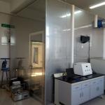
1 The entire cubic combustion chamber is assembled on site using
color steel plates.
2 Internal dimensions: L3000*W3000*H3000 (mm)
3 Structure: There is a glass observation window on the front, and
a transparent sealed window is set on each of the two opposite
walls. The size is: 100mmx100mm, allowing the light beam of the
horizontal light measuring device to pass through. The center of
the sealed window is 2150mm above the ground. There are several
vents at the bottom, and the vents are 100x500mm (50 square
centimeters)
4 An exhaust fan is installed on the top.
Light measurement system:
1. Light source: imported quartz halogen lamp, nominal power: 100W;
nominal voltage: 12V; accuracy: ±0.01V; nominal luminous flux:
2000~3000Lm, nominal color temperature: 2800K~3200K, meeting the
requirements of GB/T17651.1 5.2.
2 Receiver: Silicon photocell, amplified by the board, input to the
computer through the I/O board, meeting the requirements of
GB/T17651.1, and the spectral response matches the photometer of
the International Commission on Illumination (CIE).
3 Installation: Installed at one end of a tube with a length of
150, and the other end is a dustproof window. The inner wall of the
tube is glossy black and anti-reflective.
4 The transmittance of 0% means no light passes through, and the
transmittance of 100% means that the light passes through
completely without obstruction.
5 Measurable transmittance range (0~100)%.
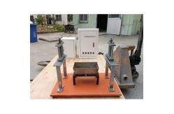
Standard fire source:
1 The fire source is 1.0L alcohol configuration: 90% ethanol, 4%
methanol, and 6% water.
2 Alcohol tray (combustion boat): stainless steel, 1.0mm thick,
bottom: 210x110mm, top: 240x140mm, height 80mm.
3 Installation position: The height of the alcohol tray from the
ground is 100mm to allow air circulation.
Smoke mixing:
1 Use a desktop fan to evenly distribute the smoke in the
combustion chamber. The fan shaft is 250mm above the ground, 500mm
from the wall, and the air volume is 7 cubic meters per minute.
During the test, the air is blown horizontally by the fan.
Blank test:
1 The purpose is to adjust the combustion chamber to the specified
temperature, and burn the alcohol lamp to make the temperature of
the combustion chamber reach: 25±5℃.
Temperature measuring device:
1 A temperature sensor is installed on the inner surface of the
door at a height of 1.5m from the ground and 0.5m from the wall to
monitor the temperature of the laboratory.
Accessories List
| No. | Name | Model | Quantity |
| 1 | Solid-state relay | SSR-40DA /250V two-phase 40A | 3 pcs |
| 2 | Circuit breaker | DZ47LE-32/230V/C32 32A | 2 pcs |
| 3 | Temperature sensor | K type Φ5.0*150 with wire L=2M | 1 pc |
| 4 | Temperature controller | RKC-CD701 or TMC-7210 size 72*72MM | 1 pc |
| 5 | Time relay | ATR02-B2 | 2 pcs |
| 6 | Counter | SVN-DS41A | 1 pc |
| 7 | Ignition device | CJ120 | 1 pc |
| 8 | Relay | 220V/14P | 4 sets |
| 9 | AC contactor | GMC-18 | 1 pc |
| 10 | Solenoid valve | Model:4v110-06/AC220V | 1 pc |
| 11 | Fan | APB35D,70W | 1 set |
| 12 | Filter | 25%,50%,75% | 1 pc |
| 13 | Computer | Laptop | 3 pcs |