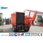
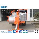
TY150 Hydraulic Puller Power Line Stringing Equipment German
Rexroth Main Pump
| Structure parameter | Pulling wheel diameter: 600 mm |
| | Groove number: 9 |
| | Max diameter of applicable pulling rope: 26 mm |
| | Weight: 6600 kg |
| | Overall dimension (length*width*height): 4800*2350*2470 mm |
| | Hoisting mode: Single point |
| Main technical performance parameter | Max intermittent pulling force: 150 kN |
| | Max continuous pulling force: 120 kN |
| | Corresponding speed: 2.5 km/h |
| | Max continuous tractive speed: 5 km/h |
| | Corresponding pulling force: 60 kN |
| Electric system | Storage battery: 24V electric starting |
| | System voltage: 24V |
| Engine | Type: Cummins 6CTA8.3-C260 |
| | Model: Straight type six-cylinder pressurizing four-stroke diesel
engine |
| | Cylinder diameter * stroke: 114*135 mm |
| | Total air output: 8.3 L |
| | Rated speed: 2200 r/min |
| | Rated power (one hour power): 194 kw |
| | Max torque: 1135 Nm |
| | Rotary speed when maximum torque: 1500 r/min |
| | Fuel consumption rate (bench test): 238 g/kw.h |
| | Cooling method: forced air cooling |
| Auxiliary oilway hydraulic system | Open type constant displacement throttle speed governing hydraulic
system is supplied oil by gear pump and controls oil liquor’s
cooling and hoisting tail bracket’s lifting of the whole hydraulic
system through hand operated direction valve and ball valve. |
| | System working pressure: 12Mpa |
| | Duplex gear pump: 1PF2G2-4X/016+014RR20MRL |
| | Fan motor: GM5-12-1FE13-S-20 |
| | Hoisting motor: J2K-305 |
| | Sleeve extension oil cylinder: 3TG110×250 |
| | Radiator: B5024 |
Taking puller’s place
1. Haul puller into selected field to put; make incoming line
groove of pulling wheel aim to rod tower center as much as
possible; the deviation range is ±7°to reduce lateral load. The
laying location and rod tower shall be 100m~150m apart, when
deviating from this range, the pulling wheel and pulling wheel
cover shall be worn out in the process of traction.
2. After determining the location of puller, start adjusting
working location of puller (given as figure 1). Retract fore
stabilizer completely; make back stabilizer be adjusted to suitable
location and insert pin shaft. Here the puller is in working
position.
3. Anchoring puller (given as figure 3). Center stressing direction
of anchor bed shall align with stretch direction of anchor in order
to make anchor bear pulling force and not bear lateral force. When
anchoring, anchor block, steel wire rope loop, shackle, lever block
or double hook with above 10-ton stress shall be used; directly
pre-tension the anchor after jointing.
4. Two anchor points in the forepart of puller are to adjust the
consistency of puller and wire tower direction. If the deviation of
puller and wire tower is more than 10°, the double-end anchor in
the forepart shall be adjusted to correct.