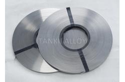
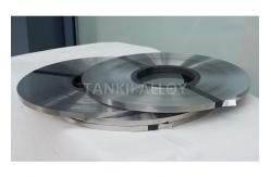
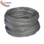
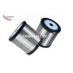
1Cr13Al4 FeCrAl alloy Bright Flat Strip/ Wide Strip for Resistors
Use
Fecral Alloys and Nickel-chromium alloys have been chosen to be the
resistive material for embedded resistor because nickel-chromium
alloys possess high electrical resistivity that is widely used for
thin film resistors [1, 2]. The sheet resistance of nickel-chrome
alloy film containing 20% chromium can be as high as 2-3 kilo ohms
and still maintain good stability. The temperature coefficient 1 of
resistance (TCR) for bulk nickel-chrome alloy is about 110 ppm/°C.
By alloying a small amount of silicon and aluminum with
nickel-chromium, the temperature stability is further improved.
Application:
Resistors embedded in a printed wiring board will be an enabler for
miniaturizing packages with higher reliability and improved
electrical performance. Integrating the resistor functionality into
the laminate substrate frees up the PWB surface area consumed by
discrete components, enabling increased device functionality by the
placement of more active components. Nickel-chromium alloys possess
high electrical resistivity, which make them practical for use in a
variety of applications. Nickel and chromium are alloyed with
silicon and aluminum to improve temperature stability and lower the
thermal coefficient of resistance. A thin film resistive layer
based on nickel-chromium alloys has been deposited continuously
onto rolls of copper foil to create a material for embedded
resistor applications. The thin film resistive layer sandwiched
between copper and laminate can be selectively etched to form
discrete resistors. The chemicals for etching are common in PWB
production processes. By controlling the thickness of the alloys,
sheet resistance values from 25 to 250 ohm/sq. are obtained. This
paper will compare two nickel-chromium materials in their etching
methodologies, uniformity, power handling, thermal performance,
adhesion and etching resolution.
| Brand name | 1Cr13Al4 | 0Cr25Al5 | 0Cr21Al6 | 0Cr23Al5 | 0Cr21Al4 | 0Cr21Al6Nb | 0Cr27Al7Mo2 |
| Main chemical composition% | Cr | 12.0-15.0 | 23.0-26.0 | 19.0-22.0 | 22.5-24.5 | 18.0-21.0 | 21.0-23.0 | 26.5-27.8 |
| Al | 4.0-6.0 | 4.5-6.5 | 5.0-7.0 | 4.2-5.0 | 3.0-4.2 | 5.0-7.0 | 6.0-7.0 |
| RE | opportune
amount | opportune
amount | opportune
amount | opportune
amount | opportune
amount | opportune
amount | opportune
amount |
| Fe | Rest | Rest | Rest | Rest | Rest | Rest | Rest |
| | | | | | | Nb0.5 | Mo1.8-2.2 |
Max.continuous
service temp.of
element (ºC) | 950 | 1250 | 1250 | 1250 | 1100 | 1350 | 1400 |
Resistivity
μΩ.m,20ºC | 1.25 | 1.42 | 1.42 | 1.35 | 1.23 | 1.45 | 1.53 |
Density
(g/cm3 ) | 7.4 | 7.10 | 7.16 | 7.25 | 7.35 | 7.10 | 7.10 |
Thermal
conductivity
KJ/m.h.ºC | 52.7 | 46.1 | 63.2 | 60.2 | 46.9 | 46.1 | 45.2 |
Coefficient of
lines expansion
α×10-6/ºC | 15.4 | 16.0 | 14.7 | 15.0 | 13.5 | 16.0 | 16.0 |
| Melting pointºC | 1450 | 1500 | 1500 | 1500 | 1500 | 1510 | 1520 |
Tensile strength
Mpa | 580-680 | 630-780 | 630-780 | 630-780 | 600-700 | 650-800 | 680-830 |
Elongation at
rupture % | >16 | >12 | >12 | >12 | >12 | >12 | >10 |
Variation of
area % | 65-75 | 60-75 | 65-75 | 65-75 | 65-75 | 65-75 | 65-75 |
Repeat bending
frequency(F/R) | >5 | >5 | >5 | >5 | >5 | >5 | >5 |
| Hardness(H.B.) | 200-260 | 200-260 | 200-260 | 200-260 | 200-260 | 200-260 | 200-260 |
Micrographic
structure | Ferrite | Ferrite | Ferrite | Ferrite | Ferrite | Ferrite | Ferrite |
Magnetic
properties | Magnetic | Magnetic | Magnetic | Magnetic | Magnetic | Magnetic | Magnetic |