
Shell and Tube Heat Exchanger | ASME Certified | Stainless Steel
|
|
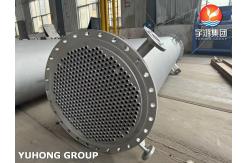
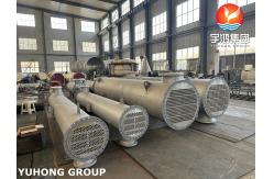
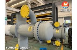
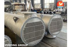
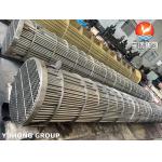
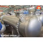
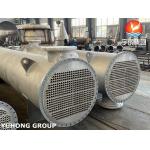
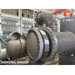
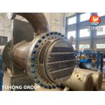
Shell and Tube Heat Exchanger | ASME Certified | Stainless Steel What is shell and tube heat exchanger (STHE)? A shell and tube heat exchanger (STHE) is the most widely used type of heat exchanger in industrial applications due to its robustness, versatility, and ability to handle high pressures and temperatures. It consists of a shell (a large pressure vessel) with a bundle of tubes inside. One fluid flows through the tubes (tube side), and the other flows outside the tubes within the shell (shell side). Heat is transferred between the two fluids through the tube walls. STHEs are governed by two key standards: 1.ASME Boiler and Pressure Vessel Code (BPVC), Section VIII, Division 1: Ensures pressure vessel safety. 2.TEMA (Tubular Exchanger Manufacturers Association) Standards: Defines mechanical design, tolerances, and fabrication practices. Key Technical Details as per ASME and TEMA 1.Design Standards ASME BPVC Section VIII, Div. 1: -Covers pressure boundary design (shell, tubesheets, channels). -Requires calculations for minimum thickness, nozzle reinforcement, and hydrostatic testing. TEMA Standards (Classes R, C, B): -Class R: Severe refinery and process applications (high pressures/temperatures). -Class C: General commercial/industrial service. -Class B: Chemical process service (corrosive environments). 2. Components & Configuration
TEMA Designation Example: AES: -A: Front head (bolted cover). -E: One-pass shell. -S: Floating rear head (pull-through bundle). 3. Thermal Design Heat Duty (Q):Q=U⋅A⋅ΔTLMTD : Overall heat transfer coefficient (W/m²·K). : Heat transfer area (tube OD × length × number of tubes). : Log Mean Temperature Difference (corrected for flow arrangement). Flow Arrangements: -Counterflow: Highest thermal efficiency. -Parallel Flow: Simpler but lower efficiency. -Crossflow: Common in condensers. Effectiveness-NTU Method: 4. Mechanical Design Shell & Tube Dimensions: -Shell ID: Determined by tube bundle layout (triangular, square, rotated square). -Tube pitch: Minimum 1.25 × tube OD (to allow cleaning). Baffle Design: -Segmental baffles (20–50% cut) with spacing per TEMA (min 1/5 shell ID or 2"). -No-Tubes-In-Window (NTIW): Eliminates dead zones. Pressure Drop: -Shell side: Optimized via baffle spacing/cut. -Tube side: Function of fluid velocity and tube length. 5. Material Selection
6. ASME Compliance & Testing Hydrostatic Test: -1.5 × design pressure (ASME VIII-1 UG-99). -Test both shell and tube sides separately. Pneumatic Test: -1.1 × design pressure (if hydrostatic testing is impractical). NDT Requirements: -RT (radiographic testing) for welds. -PT (dye penetrant) or MT (magnetic particle) for surface cracks. 7. Common Applications Oil & Gas: Preheaters, coolers, condensers. Power Plants: Steam condensers, feedwater heaters. Chemical Industry: Reactor cooling, distillation. HVAC: Chillers, district heating. Advantages & Limitations
|
|||||||||||||||||||||||||||||||||||||
| Product Tags: Assembly Shell and Tube Heat Exchanger ASME Shell and Tube Heat Exchanger TEMA Shell and Tube Heat Exchanger |
|
Shell And Tube Heat Exchanger API 660 ASME U Stamp For Petrochemical Industry Application |
|
API 660 Shell And Tube Heat Exchanger TEMA Standard ASME U Stamp ASME VIII |
|
Fixed Tubesheet Shell and Tube Heat Exchanger AEL, BEM, NEN Type TEMA Class |
|
Shell and Tube Heat Exchanger API Standard 660, ASME VIII Division 1, TEMA R CLASS |
|
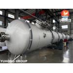
Heavy-duty Exchangers Floating Head Type H-AES Type TEMA RCB TEMA R CERTIFICATE |
|
Floating Head Type Shell and Tube Heat Exchanger NACE, HIC, SSC, ASME VIII DIV.1 |