
Mega 2560 R3 for Funduino Mega 2560 R3 / ATMega2560 / ATMega16U2
|
Detailed Product Description
|
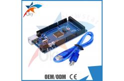
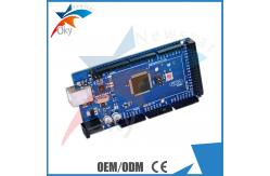
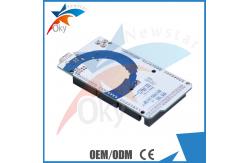
Funduino Mega 2560 Overview(100% Compatible for Ardui no): The Mega 2560 is a microcontroller board based on the ATmega2560.
It has 54 digital input/output pins (of which 15 can be used as PWM outputs), 16 analog inputs, 4 UARTs (hardware serial ports), a 16 MHz crystal oscillator, a USB connection, a power jack, an ICSP header, and a reset button. It contains everything needed to support the microcontroller; simply connect it to a computer with a USB cable or power it with a AC-to-DC adapter or battery to get started. The Mega is compatible with most shields designed for the Duemilanove or Diecimila. The Mega 2560 is an update to the Mega, which it replaces. The Mega2560 differs from all preceding boards in that it does not
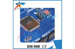
use the FTDI USB-to-serial driver chip. Instead, it features the
ATmega16U2 (ATmega8U2 in the revision 1 and revision 2 boards)
programmed as a USB-to-serial converter. Revision 2 of the Mega2560 board has a resistor pulling the 8U2 HWB
line to ground, making it easier to put into DFU mode. Revision 3 of the board has the following new features: 1.0 pinout: added SDA and SCL pins that are near to the AREF pin
and two other new pins placed near to the RESET pin, the IOREF that
allow the shields to adapt to the voltage provided from the board.
In future, shields will be compatible both with the board that use
the AVR, which operate with 5V and with the Due that operate with
3.3V. The second one is a not connected pin, that is reserved for
future purposes. Stronger RESET circuit. Atmega 16U2 replace the 8U2. Specifications:
Mega 2560 Power: The Mega can be powered via the USB connection or with an external
power supply. The power source is selected automatically. External (non-USB) power can come either from an AC-to-DC adapter
(wall-wart) or battery. The adapter can be connected by plugging a
2.1mm center-positive plug into the board's power jack. Leads from
a battery can be inserted in the Gnd and Vin pin headers of the
POWER connector. The board can operate on an external supply of 6 to 20 volts. If
supplied with less than 7V, however, the 5V pin may supply less
than five volts and the board may be unstable. If using more than
12V, the voltage regulator may overheat and damage the board. The
recommended range is 7 to 12 volts. The power pins are as follows: VIN. The input voltage to the board when it's using an external
power source (as opposed to 5 volts from the USB connection or
other regulated power source). You can supply voltage through this
pin, or, if supplying voltage via the power jack, access it through
this pin. 5V. This pin outputs a regulated 5V from the regulator on the
board. The board can be supplied with power either from the DC
power jack (7 - 12V), the USB connector (5V), or the VIN pin of the
board (7-12V). Supplying voltage via the 5V or 3.3V pins bypasses
the regulator, and can damage your board. We don't advise it. 3V3. A 3.3 volt supply generated by the on-board regulator. Maximum
current draw is 50 mA. GND. Ground pins. IOREF. This pin on the board provides the voltage reference with
which the microcontroller operates. A properly configured shield
can read the IOREF pin voltage and select the appropriate power
source or enable voltage translators on the outputs for working
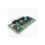
with the 5V or 3.3V. The Product Image: Company Pictures:
|
||||||||||||||||||||||||
| Product Tags: arduino development kit arduino development board |
Related Products
|
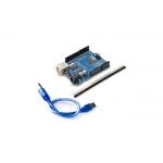
Arduino UNO R3 ATmega328P-AU Development Board ImProved Version CH340G |
|
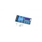
XY-L30A Battery Charge Controller Module Overcharging Protection |
|
XY-L10A Battery Charge Control Module DC6 60 60v |
|
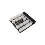
ATX 17x 6Pin Power Supply Breakout Board 12V For Ethereum |
|
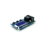
OEM ODM Pure Sine Wave Inverter Driver Board PIC16F716+IR2110S |
|
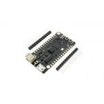
BlE ESP-32 CH340G Wireless Development Board For Arduino |
Email to this supplier