|
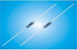
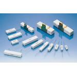
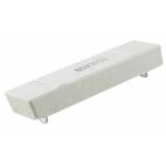
1W Precision Metal Film Resistor Quick Detail: · CECC released products with low TCRs over a wide resistance range · Resistance tolerance down to 0.05% · Express delivery available · Low noise and negligible voltage coefficient · Screened parts available for critical applications · Temperature Coefficient of Resistance down to 5 ppm/°C · Options for RoHS compliant and Lead bearing wire finishes Description: Metal film resistors are a fixed form type resistor. They are constructed out of a ceramic carrier with a thin pure metal film around it, that functions as resistive material. Applications: -Telecome -Test and Measurement -Pure tin plating provides compatibility with lead (Pb)-free and lead containing soldering processes Specifications: | 1. General 1.1 Scope This specification is available for Metal Film Fixed Resistor manufactured by,it accords with RoHS test of Environment related substance requirement. 1.2 Type designation (example) The type designation shall be in the following form and as specified. MF 1/4 W 10K J T52 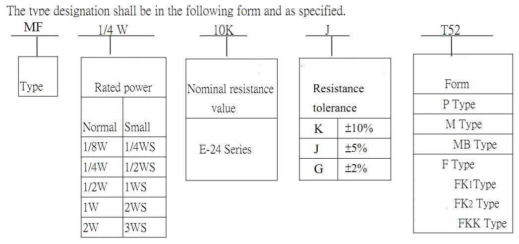 1.3 Rated power Rated power is maximum power which can be continuously loaded at specified ambient temperature 70℃,as Table-1;however when the ambient temperature exceeds 70℃,rated power should be determined from the derating curve of Fig.1. | | Table-1 | Type | Rated power | Maximum working voltage | Maximum overload voltage | Dielectric withstanding voltage | Resistance Range(Ω) | | Normal size | MF1/8W | 0.125W | 150V | 300V | 300V | 1Ω~1MΩ | | MF1/4W | 0.25W | 250V | 500V | 350V | 1Ω~10MΩ | | MF1/2W | 0.5W | 300V | 700V | 400V | 1Ω~10MΩ | | MF1W | 1W | 350V | 800V | 450V | 1Ω~10MΩ | | MF2W | 2W | 500V | 800V | 450V | 1Ω~10MΩ | | MF3W | 3W | 500V | 800V | 500V | 1Ω~10MΩ | | MF5W | 5W | 500V | 1000V | 500V | 1Ω~10MΩ | | Small size | MF1/4WS | 0.25W | 150V | 300V | 300V | 1Ω~10MΩ | | MF1/2WS | 0.5W | 250V | 700V | 350V | 1Ω~10MΩ | | MF1WS | 1W | 300V | 800V | 400V | 1Ω~10MΩ | | MF2WS | 2W | 350V | 800V | 450V | 1Ω~10MΩ | | MF3WS | 3W | 500V | 1000V | 450V | 1Ω~10MΩ | | MF5WS | 5W | 500V | 1000V | 500V | 1Ω~10MΩ | Figure 1 Power derating curve 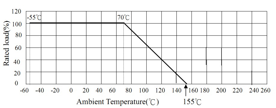 1.4 Rated voltage The rated voltage shall be the D.C. or A.C.(R.M.S. at power frequency) voltage which corresponds the rated power and the value of which is calculated from the formula below. | E=√(P×R) Where E: Rated voltage(V) P: Rated power(W) R: Nominal resistance(Ω) Operating Temperature Range:-55℃~+155℃ 2. Construction 2.1 External dimensions The dimensions shall be satisfied with [5. External dimensions]. 2.2 Structure diagram The construction of resistor (CF series) shall be as follows: 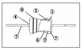 | | Item | Material | | 1 | Ceramic core | High alumina ceramic is used. | | 2 | Resistor element | The resistor element shall consist of metal film. | | 3 | Terminal | Tinned iron cap. | | 4 | Connection | The lead wire, which is plated with solder, shall be mounted to the caps by welding process. | | 5 | Lead wire | Soldered or tinned annealed wire. | | 6 | Undercoat painting | Electric insulation resin. | | 7 | Finishing painting | Epoxy resin is used. | | 8 | Indication | Color code. | | | 2.3 Terminal caps The caps shall be securely connected with the resistor element electrically and mechanically. 2.4 Resistor body color Table-2 | Normal size | Small size | | Type | Color | Type | Color | | MF1/8W,MF1/4W, MF1/2W,MF1W, MF2W,MF3W, MF5W | Sky blue | MF1/4WS ,MF1WS, MF2WS,MF3WS, 5WS | Sky blue | 2.5 Indication The indication shall be satisfied with [4. Indication]. 3. Characteristics Table-3 | Item | Performance | Test methods(Conform to JIS C 5202) | | Temperature Coefficient | T.C.R | ±350 (PPM/℃) | +0~ -500 (PPM/℃) | +0~ -700 (PPM/℃) | +0~ -1500 (PPM/℃) | Comply with 5.2 R1-R0 R0(T1-T0) R0: Resistance value at room temp.( T0). R1:Resistance value at room temp.plus 100℃ (T1) | | Resistance Value | <47KΩ | 47KΩ ~ 100KΩ | 101KΩ ~ 330KΩ | 331KΩ ~ 10MΩ | | Short time overload | Within ±(1%+0.05Ω). No evidence of mechanical damage. | Comply with 5.5 Rated voltage×2.5 times,5s But not to exceed maximum overload voltage. (See table-1) | | | Item | Performance | Test methods(Conform to JIS C 5202) | | Insulation Resistance | 104MΩ Mini. 104MΩ or more. | Comply with 5.6 V-block method Resistor shall be tested at DC 500V for 60 seconds. | | Dielectric Withstanding Voltage | No evidence of flashover mechanical damage, arcing or insulation breakdown. | Comply with 5.7 Constant pressure, V-block method Resistor shall be tested at AC potential respectively for 60 seconds.(See table-1) | | Pulse overload | Within ±(2%+0.05Ω) | Comply with 5.8 Rated voltage X 4 times, 10000 cyc.(1s ON, 25s OFF) But not to exceed maximum pulse voltage.(See table-1) | | Terminal strength | No evidence of mechanical damage. | Comply with 6.1 | Tensile strength | mm Diameter | Tensile force N(kgf) | Time | | Φ0.38mm~0.50mm | 5(0.51) | 10±1 second | | Φ0.50mm~0.68 mm | 10(1.02) | Torsion strength:To bend the lead wire at the point of about 6mm~ | | | | Item | Performance | Test methods(Conform to JIS C 5202) | | Insulation Resistance | 104MΩ Mini. 104MΩ or more. | Comply with 5.6 V-block method Resistor shall be tested at DC 500V for 60 seconds. | | Dielectric Withstanding Voltage | No evidence of flashover mechanical damage, arcing or insulation breakdown. | Comply with 5.7 Constant pressure, V-block method Resistor shall be tested at AC potential respectively for 60 seconds.(See table-1) | | Pulse overload | Within ±(2%+0.05Ω) | Comply with 5.8 Rated voltage X 4 times, 10000 cyc.(1s ON, 25s OFF) But not to exceed maximum pulse voltage.(See table-1) | | Terminal strength | No evidence of mechanical damage. | Comply with 6.1 | Tensile strength | mm Diameter | Tensile force N(kgf) | Time | | Φ0.38mm~0.50mm | 5(0.51) | 10±1 second | | Φ0.50mm~0.68 mm | 10(1.02) | Torsion strength:To bend the lead wire at the point of about 6mm~ | | 4. Indication Color Code | Color | 1st figure | 2nd figure | 3RD figure | Multiplier | Tolerance | | Black | 0 | 0 | 0 | 100 | | | | Brown | 1 | 1 | 1 | 101 | ±1% | (F) | | Red | 2 | 2 | 2 | 102 | ±2% | (G) | | Orange | 3 | 3 | 3 | 103 | | | | Yellow | 4 | 4 | 4 | 104 | | | | Green | 5 | 5 | 5 | 105 | ±0.5% | (D) | | Blue | 6 | 6 | 6 | 106 | ±0.25% | (C) | | Violet | 7 | 7 | 7 | 107 | ±0.1% | (B) | | Gray | 8 | 8 | 8 | | ±0.05% | (A) | | White | 9 | 9 | 9 | | | | | Gold | | | | 10-1 | ±5% | (J) | | Silver | | | | 10-2 | ±10% | (K) | | Plain | | | | | ±20% | (M) | 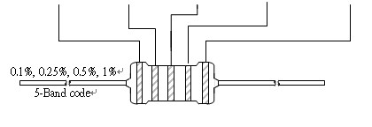 5. External dimensions P type 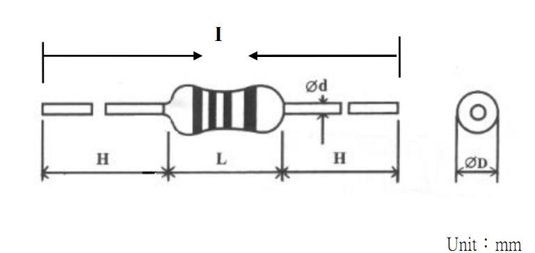 | Type | Dimensions | | Normal Size | Small Size | I±2.0 | L±1.0 | ψD | ψd±0.05 | H±2.0 | | MF1/8W | MF1/4WS | 60 | 3.2 | 1.8±0.5 | 0.43 | 28 | | MF1/4W | MF1/2WS | 60 | 6.5 | 2.3±0.5 | 0.45 | 28 | | MF1/2W | MF1WS | 60 | 9.0 | 3.2±0.5 | 0.50 | 28 | | MF1W | MF2WS | 60 | 11.5 | 4.5±1.0 | 0.68 | 25 | | 73 | 11.5 | 4.5±1.0 | 0.68 | 31 | | MF2W | MF3WS | 60 | 15.5 | 5.0±1.0 | 0.68 | 23 | | 81 | 15.5 | 5.0±1.0 | 0.68 | 33 | | MF3W | MF5WS | 94 | 17.5 | 6.0±1.0 | 0.68 | 38 | | MF5W | 94 | 24.5 | 8.0±1.0 | 0.68 | 35 | 5.2 Axial Lead Taping TXX Type  | Type | Taping | Dimensions | | Normal Size | Small Size | L | W | P | L1-L2 Max. | T | Z Max. | R Max. | t Max. | e Max. | S Max. | | MF1/8W | MF1/4WS | T26 | 3.2±0.5 | 26+1 -0 | 5±0.5 | 0.5 | 6±0.5 | 1.2 | 0 | 3.0 | 0.6 | 0.5 | | T52 | 3.2±0.5 | 52±1.0 | 5±0.5 | 1.0 | 6±0.5 | 1.2 | 0 | 3.0 | 0.6 | 0.5 | | MF1/4W | MF1/2WS | T26 | 6.5±0.5 | 26+1 -0 | 5±0.5 | 0.5 | 6±0.5 | 1.2 | 0 | 3.0 | 0.6 | 0.5 | | T52 | 6.5±0.5 | 52±1.0 | 5±0.5 | 1.0 | 6±0.5 | 1.2 | 0 | 3.0 | 0.6 | 0.5 | | MF1/2W | MF1WS | T52 | 9.0±1.0 | 52±1.0 | 5±0.5 | 1.0 | 6±0.5 | 1.2 | 0 | 3.0 | 0.6 | 0.5 | | MF1W | MF2WS | T52 | 11.5±1.0 | 52±1.0 | 5±0.5 | 1.0 | 6±0.5 | 1.2 | 0 | 3.0 | 0.6 | 0.5 | | T66 | 11.5±1.0 | 66±1.0 | 5±0.5 | 1.0 | 6±0.5 | 1.2 | 0 | 3.0 | 0.6 | 0.5 | | MF2W | MF3WS | T52 | 15.5±1.0 | 52±1.0 | 10±0.5 | 1.0 | 6±0.5 | 1.2 | 0 | 3.0 | 0.6 | 0.5 | | T73 | 15.5±1.0 | 73±1.0 | 10±0.5 | 1.0 | 6±0.5 | 1.2 | 0 | 3.0 | 0.6 | 0.5 | | MF3W | MF5WS | T84 | 17.5±1.5 | 84±1.0 | 10±0.5 | 1.0 | 6±0.5 | 1.2 | 0 | 3.0 | 0.6 | 0.5 | | MF5W | T84 | 24.5±1.5 | 84±1.0 | 10±0.5 | 1.0 | 6±0.5 | 1.2 | 0 | 3.0 | 0.6 | 0.5 | 5.3 MB Type &M Type&MK Type MB  | Watts | Dimensions (mm) | | D | L | P±1.0 | H1±1.0 | H2±0.5 | t±0.15 | qMax | | 1/2w,1ws | 3.2±0.5 | 9.0±1.0 | 12.5/15 | 10.5 | 4.5 | 1.2 | 3 | | 1w,2ws | 4.5±1.0 | 11.5±1.0 | 15 | 10.5 | 4.5 | 1.25 | 3 | | 2w,3ws | 5.0±1.0 | 15.5±1.0 | 20 | 10.5 | 4.5 | 1.25 | 3 | | 3W5WS | 6.0±1.0 | 17.5±1.0 | 25 | 10.5 | 4.5 | 1.25 | 3 | | 5W | 8.0±1.0 | 24.5±1.0 | 30 | 10.5 | 4.5 | 1.25 | 3 | M | Watts | Dimensions (mm) | | ΦD | L | P±1.0 | H±1.0 | | 1/8w,1/6w | 1.8±0.3 | 3.2±0.5 | 6 | 8 | | 1/4w,1/2ws | 2.3±0.5 | 6.5±0.5 | 10 | 8 | | 1/2w,1ws | 3.2±0.5 | 9.0±1.0 | 12.5/15 | 10 | | 1w,2ws | 4.5±1.0 | 11.5±1.0 | 15 | 10 | | 2w,3ws | 5.0±1.0 | 15.5±1.0 | 20 | 10 | | 3w | 6.0±1.0 | 17.5±1.0 | 25 | 10 | | 5w | 8.0±1.0 | 24.5±1.0 | 30 | 10 | MK  | Watts | Dimensions (mm) | | D | L | P±1.0 | H±1.0 | H1±1.0 | | 1/2w,1ws | 3.2±0.5 | 9.0±1.0 | 12.5 | 10 | 4.5 | | 1w,2ws | 4.5±1.0 | 11.5±1.0 | 15 | 10 | 4.5 | | 2w,3ws | 5.0±1.0 | 15.5±1.0 | 20 | 10 | 4.5 | | 3W5WS | 6.0±1.0 | 17.5±1.0 | 25 | 10 | 4.5 | 5.4 F Type &FK2Type&FKK Type  | Watts | Dimensions (mm) | | ΦD | L | P±2.0 | E Max | H±1.0 | | 1/2w,1ws | 3.2±0.5 | 9.0±1.0 | 6 | 3.5 | 5-8 | | 1w,2ws | 4.5±1.0 | 11.5±1.0 | 8 | 3.5 | 5-8 | | 2w,3ws | 5.0±1.0 | 15.5±1.0 | 8 | 3.5 | 5-8 | | 3w | 6.0±1.0 | 17.5±1.0 | 8 | 3.5 | 5-8 | | Watts | Dimensions (mm) | | ΦD | L | P±2.0 | E Max | H±1.0 | | 1/2w,1ws | 3.2±0.5 | 9.0±1.0 | 6 | 3.5 | 5-8 | | 1w,2ws | 4.5±1.0 | 11.5±1.0 | 8 | 3.5 | 5-8 | | 2w,3ws | 5.0±1.0 | 15.5±1.0 | 8 | 3.5 | 5-8 | | 3w | 6.0±1.0 | 17.5±1.0 | 8 | 3.5 | 5-8 | FKK  | Watts | Dimensions(mm) | | ΦD | L | P±1.0 | E Max | H1±1.0 | H2±1.0 | | 1/2w,1ws | 3.2±0.5 | 9.0±1.0 | 5-7 | 3.5 | 8 | 4.5 | | 1w,2ws | 4.5±1.0 | 11.5±1.0 | 5-9 | 3.5 | 8 | 4.5 | | 2w,3ws | 5.0±1.0 | 15.5±1.0 | 5-9 | 3.5 | 8 | 4.5 | | 3w | 6.0±1.0 | 17.5±1.0 | 5-10 | 3.5 | 8 | 4.5 | | 5 Package 5.1 Tape in box packing (Ammo packing) 5.1.1 Indication (1) Customer Part No. (2) Manufacturer Part No. (3) Quantity (4) Manufacturer  6.1.2 Packing box size and quantity | Type | Form | Quantity | Dimensions (mm) | | Normal Size | Small Size | L | W | H | | MF1/8W | MF1/4WS | T26 | 5000 PCS | 260 | 50 | 67 | | T52 | 5000 PCS | 260 | 80 | 72 | | MF1/4W | MF1/2WS | T26 | 5000 PCS | 260 | 50 | 100 | | T52 | 5000 PCS | 260 | 80 | 100 | | MF1/2W | MF1WS | T52 | 2000 PCS | 260 | 80 | 85 | | MF1W | MF2WS | T52 | 1000 PCS | 260 | 80 | 85 | | T67 | 1000 PCS | 260 | 85 | 92 | | MF2W | MF3WS | T52 | 1000 PCS | 260 | 80 | 100 | | T73 | 1000 PCS | 260 | 95 | 92 | | MF3W | MF5WS | T84 | 500PCS | 260 | 110 | 75 | | MF5W | T84 | 250PCS | 260 | 110 | 75 | | | 6.2 Tape in box Bulk (Ammo Bulk) 6.2.1 Indication (5) Customer Part No. (6) Manufacturer Part No. (7) Quantity (8) Manufacturer  6.2.2 Packing box size and quantity | Type | Form | Quantity | Dimensions (mm) | | Normal Size | Small Size | L | W | H | | MF1/8W | MF1/4WS | P | 10000 PCS | 240 | 140 | 76 | | Moulding | 10000 PCS | 240 | 140 | 76 | | MF1/4W | MF1/2WS | P | 10000 PCS | 240 | 140 | 76 | | Moulding | 10000 PCS | 240 | 140 | 76 | | MF1/2W | MF1WS | P | 5000 PCS | 240 | 140 | 76 | | Moulding | 5000 PCS | 240 | 140 | 76 | | MF1W | MF2WS | P | 2000 PCS | 240 | 140 | 76 | | Moulding | 2000 PCS | 240 | 140 | 76 | | MF2W | MF3WS | P | 2000 PCS | 240 | 140 | 76 | | Moulding | 2000 PCS | 240 | 140 | 76 | | MF3W | MF5WS | P | 100PCS | 240 | 140 | 76 | | Moulding | 250PCS | 240 | 140 | 76 | | MF5W | P | 50PCS | 240 | 140 | 76 | | Moulding | 50PCS | 240 | 140 | 76 | | Competitive Advantage: 1. Factory supply directly 2. Completed certificates such as UL,VDE,SGS,etc and high quality available 3. Quick delivery 4. Best after-sales services 5. OEM & ODM available  |