
LED Inverted Metallurgical Optical Microscope For University Learning A13.0205
|
|
Congratulations and Thank You for your purchase of The Microscope
WARNING
CAUTION: NEVER IMMERSE THE INSTRUMENT IN WATER OR SOLVENT
Getting Started
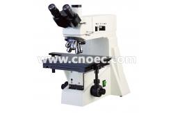
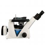
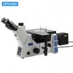
1. Filter Seat 2. Field Diaphragm Centering Screw 3. Polarizer Adjustment Lever 4. Trinocular Body 5. Objective 6 .Stage 7. Up Stop 8. Coarse Focus Control Knob 9. Fine Focus Control Knob 10. Quick Adjustment Lever
11. Eyepiece 12. .Binocular Eyepiece Set Screw 13. Field Diaphragm Adjustment Lever 14. Aperture Diaphragm Adjustment Lever 15. Power Cord 16. Power Inlet 17. Brightness Control 8. Power Switch 19. Transverse Adjustment Knob 20. Longitudinal Adjustment Knob 21. Focus Tensional Adjustment Knob
Setup Instructions 1. Remove all parts from their packing materials and retain the packaging in the event you need to transport the product. 2. Loosen the binocular eyepiece set screw install the binocular eyepiece to the optical body by removing its dust cap and inserting the dovetailed flange on the underside of the binocular eyepiece into the optical body. Secure binocular eyepiece with screw. DO NOT RELEASE THE OPTICAL BODY FORM YOUR GRASP UNTIL IT IS FIRMLY SECURED TO THE FRAME. 3. Install both field diaphragm centering levers and filter seat to the frame. 4. Install the objective into the nosepiece 5. Remove the dust caps from the eyetubes and insert both eyepieces into the optical body. 6. Connect the power cord to a suitable power supply.
Basic Operation
1. Illumination controls 1) The power switch to the illuminator and the brightness control is located on the base. The electrical system is fuse protected and the fuse holder located on the power inlet.
2)Turn on the light with the power switch, see figure 3. If the light does not appear to be ON, check the brightness control to see if it’s on a sufficiently low setting.
1. Focusing Controls
2)Focus Control Turning either of the coarse focus control knobs will raise or lower the optical body. The smallest graduation on the fine adjust knob index scale is 0.8μm of vertical.
4)re-focusing or Focus Stop Control. Use of this feature will insure that the shorter working distance objectives don’t contact the stage or specimen when using the microscope. Its use also simplifies focusing. After focusing on the specimen with the coarse adjustment by low magnification eyepiece, rotation of the lever toward the front of the microscope will set and upper limit on the coarse adjustment movement. After changing specimens or objectives, focusing is easily accomplished by rotating the coarse adjustment knob to reach the pre-focused position, then making fine adjustments with the fine adjustment knob. Focusing movement with the fine adjustment isn’t affected by using the pre-focusing lever.
3. Diopter and Interpupillary Adjustments
1)Diopter Adjustment Proper correction for individual vision is accomplished via the diopter adjustment located at the left eyepiece, see figure 5. Using the 40X magnification objective, close your left eye and bring an image into focus with your right eye only. Once the image is well focused, observe with left eye, make fine adjustments with the diopter adjustment ring to correct for your vision.
2)Proper interpupillary distance, or the distance between eyepieces, is crucial to the comfort of the user. Adjusting the interpupillary distance is accomplished through a “folding” action of the optical head, at figure 5. allowing for quick and easy adjustment.
4. Mechanical Stage Controls The mechanical stage, see figure 6. consists of three parts: 1) 1 for transverse adjustment. 2) 2 for longitudinal adjustment. 2) 3 for the quick adjustment, push this lever for move towards position quickly.
5. Vertical Illumination Alignment,
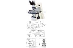
1. Trinocular Body 2.Field Diaphragm Adjustment Lever 3.Field Diaphragm Centering Screw 4.Filter Seat 5. Aperture Diaphragm Adjustment Lever 6.Focusing Lens Adjustment Lever 7.. Bulb 8. Cover 9. Screw 10. Lamp Socket 11.Lamp Centering Screw
1) The aperture diaphragm near the lamp house may be adjusted slightly to change contrast. 2) To center the incident or vertical lamp. a) Put a piece of paper and place it on the stage. Take out one objective form nosepiece and rotate the nosepiece until this objective opening hole is in position over the paper. b) Turn the power on and adjust the brightness control to establish sufficient light. c) This paper will allow for focusing of the lamp filament on it. If the filament image is not centered in the overpass hole, reduce the aperture diaphragm, loosen the screw , remove the cover and adjust the lamp centering screw obtain a uniform image. Adjust the focusing lens lever until a sharp image of the lamp filament is attained, refer to figure 8 for this step.
3) Reinstall the objective again. 4) Adjust the focusing control until the image clear. If brightness of field not equality, you may adjust the lamp centering screw and focusing lens lever slightly to make the brightness of field equality, then reinstall the cover. 5) Reduce the field diaphragm, If it is not centered, move it to the center using the centering lever. Adjustment can be done by opening the field diaphragm. 6)The filter seat contains a green, yellow, blue filter and ground glass, you may turn anyone to the light path to obtain an image of good quality. 7) The polarizing analyzer is used in conjunction with the polarized filter cube, selected by pushing in the blue filter rod, see figure 9. Push polarizer to working position, rotate it while watching the brightness in the field and let the polarizer and analyzer orthogonally. 8) The white push rod to the upper left of the trinocular head will send 100% of the image light to the binocular eyepieces or to the top port. It satisfy high-grape photography.
Changing the Light Bulb
2. Loose the screw and remove the cover, see figure 8. 3. The halogen bulb can be removed by grasping the bulb and pulling it firmly from its fixture. Take care not to touch the lamp with bare fingers, as the lamp will be hot. 4. Insert the new halogen bulb into the same fixture. When installing the new bulb, be careful not to touch the glass with your fingers. The new lamp should be supplied in a plastic protective envelope. If not, use a tissue or other medium to grasp the bulb. This will prevent contamination from your hand from reducing the bulb’s intensity and life. 5. Reinstall cover to the frame. 6. If necessary, you may need to readjust the bulb as previously described.
Preventative Maintenance
1. Cleaning frame and stage Disconnect the plug from mains socket before cleaning. Clean the frame and stage with a soft cloth moistened with a mild detergent solution. Be sure the instrument is dry before using. 2. Cleaning optical parts Microscope eyepieces and objectives are coated. They should not be wiped while dry as dirt or dust may scratch the coating. It is best to remove parts from the frame prior to cleaning. Always blow loose dust away first. Use cotton swabs or lens tissue moistened with a lens cleaner or a small amount of alcohol, then wipe the surface clean with a good quality lens tissue. Solvents such as Xylene should NOT be used as cleaner. 3. Cleaning 100X oil immersion lens The immersion oil should be removed from the lens at the end of each workday using cotton swabs or lens tissue moistened with a lens cleaner or a small amount of alcohol. DO NOT DISASSEMBLE OBJECTIVE LENSES. |
| Product Tags: reflected light microscope halogen lamp microscope |
|
OPTO EDU A13.3601 Binocular Metallurgical Microscope Transmit And Reflect Light |
|
A13.1013 Infinity Metallurgical Optical Microscope For Industry Inspection |
|
OPTO-EDU A13.2607 Inverted Metallurgical Optical Microscope |
|
Infinity Color Metallurgical Optical Microscope Corrected Optical System A13.0912-A |
|
OPTO-EDU A13.2607 Invered MetallInvered Metallurgical Microscope, BF,PL |
|
OPTO-EDU A13.2606 Invered Metallurgical Microscope, Reflect Light, BF |